I think i explain it badly.
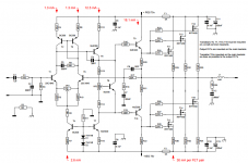
When heatsink is cool the bias is 30ma per pair FETs.
After some minutes the temperature of hetsink is 40°C.
on 40°C the bias is 1.16V across 10R resistor and when i try to cool it by fan or anything like hardryer, the bias increases.
I want to know if there is something wrong with it, how to handle it.
Thank you.
Nothing wrong. All OK. You want the bias to decrease with rising temperature. It's OK if it decreases a little. The worst thing is if bias increases with temperature, making the amp warm up more, increase bias, warm up even more... leading to thermal runaway. Your situation is the opposite and that was the intention of the designer.
You can never get it exactly constant in a mass produced item because of component tolerances and variations. So you plan to have a slight negative trend with random component variations, as you do. Enjoy some music.
1uF allows a 34ms RC.
That's low for bass only.
There is only 100ms for the NFB loop. That too is too low.
That's low for bass only.
There is only 100ms for the NFB loop. That too is too low.
What is the lowest frequency you want to pass?
I'll assume you choose 20Hz.
Then set the passive input filter to 80ms and set the NFB to >120ms
If you use electrolytic, then double the capacitance.
For 20Hz you end up with:
input 2u2F & 1k+33k (or 1k+36k)
NFB 220uF & 1k (This electrolytic must be oriented to suit the prevailing voltage and bypassed by inverse parallel diodes, or a aseries pair of inverse parallel diodes for more voltage to avoid alledged distortion attributable to these protection diodes. 1n4148 are good enough because current and voltage are not high).
Can you see why 10uF (for 340ms RC) would be a bad choice?
Last edited:
Hi Andrew,
Why don't you work in frequencies instead of time constants for this? It would be more easily understood by the bulk of the members. Talking about 3dB down point might be more illuminating.
-Chris
Why don't you work in frequencies instead of time constants for this? It would be more easily understood by the bulk of the members. Talking about 3dB down point might be more illuminating.
-Chris
Hi AndrewT.
I saw some subwoofer amp sch, I saw that they have 100ms NFB too.
what happens if we do not increase NFB?
Best regards.
I saw some subwoofer amp sch, I saw that they have 100ms NFB too.
what happens if we do not increase NFB?
Best regards.
the NFB limits the way the amplifier processes the signal.
If the amplifier is presented with a signal that applies a voltage to the NFB DC blocking cap, then three consequences arise (that I am aware of, there may be more).
a.) the electrolytic introduces distortion when AC signal is across it.
b.) the feedback is changed so that output impedance changes
c.) the roll off of the LF is dependent on the quality of the electroytic
All three of those consequences are reduced by ensuring the NFB cap is not presented with an AC signal across it.
The easy way to achoeve this is to make the NFB cap big. Bigger than the passs band set by the passive imput filter. Normally making NFB RC = InputRC * sqrt(2) makes a good NFB cap big enough. But D.Self has shown that this is not quite big enough to avoid a.) and you have to make the electro twice as big i.e. Electro NFB RC >= 2sqrt(2)*input RC.
Hi AndrewT.
I didn't know that, I learnd it from you.
thanks.
Oh, one stupid question: ��
In Nmos200 sch, it's said that all other resistors must be 1/2W, but in Nmos350/500 it doesn't.
Does it means we can use 1/4w resistors?
I used 1/4w resistors except output stage resistors��
thanks.
I didn't know that, I learnd it from you.
thanks.
Oh, one stupid question: ��
In Nmos200 sch, it's said that all other resistors must be 1/2W, but in Nmos350/500 it doesn't.
Does it means we can use 1/4w resistors?
I used 1/4w resistors except output stage resistors��
thanks.
Hi AndrewT.
Some of questions are answered in this topic, but they are hard to find because of many posts in it.
Fortunately 1/4W resistors will be Ok.
According to your suggestion, I used 2.2uF and 220uf caps and the amp bass responce became great.
I love bass, actually I tried to get a loud and high power bass from many amps that I had made several times.
But I couldn'd get high power boss like commerical audio systems.
I saw that many home audio systems are shaking the whole house with only a 100W subwoofer, but I couldn't get that bass with a 350W amp and a 400W 12" subwoofer.
I tried to reach a high quality and high power bass, but it seems like reaching moon on the sky!
I even got tested Nmos 500 with circuit below, quality is fine, but amp clips very soon when the volume rises , and when I decrease the gain the power sounds like a 50W amp.
I have this problem with all amps I've made.
Regards.

Last edited:
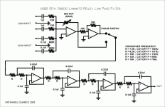
your LR8 is wrong. Q=0.742
That does not match B2
The 220nF & 100nF should be equal for a Q=0.5 to create an LR2
For LR4 you use two B2 cascaded: C1 gets doubled for Q=1/sqrt(2) and cascaded for an overall Q=0.5
For LR8 you need a higher Q for each stage so that the Q=0.5
I think you should have a Q for stages 1 & 2 that combine to give a B4 and then add on stages 3 & 4 that combine to give another B4.
For two cascaded stages with a B4 output you need to look up the Butterworth filter tables and find the required Q value for each stage. They are not Q=0.84
Last edited:
Hi guys.
I've made Nmos500 amp for a subwoofer. ( Earthquake tremor X124, 400W R.M.S)
I linked it to several Low Pass filter, but in all cases the amp has a hard clipping even in low volume.
I connected an AC power meter before the amp and saw when the power reaches to 140W and more, distortion starts.
actually i can't drive the amp with full power, at high volume the subwoofer shakes whole the house but the sound isn't clear and it clips very soon and very hard.
in low volume everything is OK and sound is clear.
why the amp goes to clipping on 30% of its power?
Thanks.
Hi chico67,
Have you checked the amplifier to see if it's oscillating? Also, check that the supply voltages are not falling under power.
Last check. Is the current limiter coming on? You need to use an oscilloscope to check these things.
-Chris
Have you checked the amplifier to see if it's oscillating? Also, check that the supply voltages are not falling under power.
Last check. Is the current limiter coming on? You need to use an oscilloscope to check these things.
-Chris
Hi chico67,
Have you checked the amplifier to see if it's oscillating? Also, check that the supply voltages are not falling under power.
Last check. Is the current limiter coming on? You need to use an oscilloscope to check these things.
-Chris
Hi anatech.
unfortunately i don't have an oscilloscope, but supply voltages is Ok.
55-0-55 transformer 700W + 30,000 uF per rails.
I checked output with a Clip indicator, its LED shows clipping very soon, even on 10% volume.
- Home
- Amplifiers
- Solid State
- Power amp under development
