attachment latest PCB Layout for NMOS, has some additional features like
- bootstrap
- VI Limiter
- Input Limiter from apex H900 Class H Amp
Thanks to apexaudio
- crowbar DC protect
- Relay free electronic turn on delay / fast off
impossibile with one-side PCB
will add in future 2 Step Class H for NMOS +/- 140 V +/- 70 V
- bootstrap
- VI Limiter
- Input Limiter from apex H900 Class H Amp
Thanks to apexaudio
- crowbar DC protect
- Relay free electronic turn on delay / fast off
impossibile with one-side PCB
will add in future 2 Step Class H for NMOS +/- 140 V +/- 70 V
Attachments
Last edited:
my nmos is working with +/-90 V since 8 months
Thank you QSA, what about the 2sk1530, is it a good candidate for irf450 replacement for NMOS amplifier? last time i was able to built the single channel quasi amplifier and it doing great but I used the irf450,It is a very good ampifier indeed, I still have these 2sk1530 so I would like to build the NMOS using it. 🙂
hi qsa
greetings any pcb pattern for diyers very compact pcb and most of all
easy to get components
thanking you
andrew lebon
greetings any pcb pattern for diyers very compact pcb and most of all
easy to get components
thanking you
andrew lebon
Thank you QSA, what about the 2sk1530, is it a good candidate for irf450 replacement for NMOS amplifier? last time i was able to built the single channel quasi amplifier and it doing great but I used the irf450,It is a very good ampifier indeed, I still have these 2sk1530 so I would like to build the NMOS using it. 🙂
oh, im talking about this NMOS200 version..
http://www.diyaudio.com/forums/atta...0734-power-amp-under-development-nmos200-.pdf
specification says max of 50 volts rail but im going to use 75 volts because thats what I have here.😛
nobody interested
to add supporting 2 Step Class H for NMOS +/- 140 V +/- 70 V
or +/- 40 and +/- 80 V ???
to add supporting 2 Step Class H for NMOS +/- 140 V +/- 70 V
or +/- 40 and +/- 80 V ???
In Nmos200 amplifier (TO247)
Quasi's DIY Audio Site: Nmos200
I replaced the fuses with 100ohm 5W resistors and i have 0V on resistors
What's the problem?
Please help!
Quasi's DIY Audio Site: Nmos200
I replaced the fuses with 100ohm 5W resistors and i have 0V on resistors
What's the problem?
Please help!
nobody interested
to add supporting 2 Step Class H for NMOS +/- 140 V +/- 70 V
or +/- 40 and +/- 80 V ???
it is obvious that you are using somebody elses thread ...to present some other amplifier ....it would be by far easier to make a new thread
this is threadjacking i presume and i wonder what is a reason to do that ....
its not my thread and actually i dont bother
my opinion is that i dont like it ...
NAD 208 amplifier use topology what you looking for,nobody interested
to add supporting 2 Step Class H for NMOS +/- 140 V +/- 70 V
or +/- 40 and +/- 80 V ???
Regards
quasi 6 FET 2nd channel test
I was able to complete the 2nd channel of QUASI 6 fet version, everything is ok from all adjustment but on the audio test (around 45 seconds maybe) the positive rail fuse suddenly blow, I removed the board from heat sink and try to find out what went wrong, It was one of the FET T11, Fet is shorted from gate to drain, I cannot find any problem on the board since I got all the adjustment right at the 1st adjusment using 100 ohms resistor to 10 ohms resistor, I suspected a fake FET irpf450 , it was the last fet I bought from a local electronics store here in philippines, I need to look for a good FET first before I proceed with the amp audio test. 🙁
I was able to complete the 2nd channel of QUASI 6 fet version, everything is ok from all adjustment but on the audio test (around 45 seconds maybe) the positive rail fuse suddenly blow, I removed the board from heat sink and try to find out what went wrong, It was one of the FET T11, Fet is shorted from gate to drain, I cannot find any problem on the board since I got all the adjustment right at the 1st adjusment using 100 ohms resistor to 10 ohms resistor, I suspected a fake FET irpf450 , it was the last fet I bought from a local electronics store here in philippines, I need to look for a good FET first before I proceed with the amp audio test. 🙁
In Nmos200 amplifier (TO247)
Quasi's DIY Audio Site: Nmos200
I replaced the fuses with 100ohm 5W resistors and i have 0V on resistors
What's the problem?
Please help!
did you tried to adjust the VR2? maybe the VR2 is set to minimum, please try to adjust first.
🙂
Yes. I adjusted the VR2 and i have the same problem.did you tried to adjust the VR2? maybe the VR2 is set to minimum, please try to adjust first.
🙂
All transistors is ok!
🙁
Yes. I adjusted the VR2 and i have the same problem.
All transistors is ok!
🙁
Check this error ..
 , it was the problem I encountered before.thanks for somebody who notice this and upload the image.😀
This is for Nmos200??😕Check this error ..View attachment 178664, it was the problem I encountered before.thanks for somebody who notice this and upload the image.😀
For this pcb??
An externally hosted image should be here but it was not working when we last tested it.
Ohh,m im sorry it was for the quasi 350 6 fet version.. try to isolate the problem in T8 area.
replace T8?Ohh,m im sorry it was for the quasi 350 6 fet version.. try to isolate the problem in T8 area.
The pcb is new with no problems.
replace T8?
The pcb is new with no problems.
You could check for orientation problem with affected area. what I did last time was I checked the datasheet for each transistor.
Hi,
I had experience like this before but the other way round. The current limiting resistor keep 'braised' (not 'popped'). I turned the pot to the middle and when I adjusted, I can see a varying current (or varying voltage across the limiting resistor) and got the job done.
Assume all other possible errors are eliminated, maybe you should turned the pot to the other end and see if the 5W pops? I never use a 5W because when it explode, it would be much messier. I use a 1/4 - 1/2 W 10ohm instead all the time for testing any of these.
NMOS 200 1st PCB fabrication
Hello, attached is my 1st PCB fabrication for NMOS200 amplifier using photo transfer method, beside is my DIY drill I used for drilling.
 🙂
🙂
Hello, attached is my 1st PCB fabrication for NMOS200 amplifier using photo transfer method, beside is my DIY drill I used for drilling.
🙂I am near to finish my Nmos200 by wiring work. Here are some pictures from where i am.
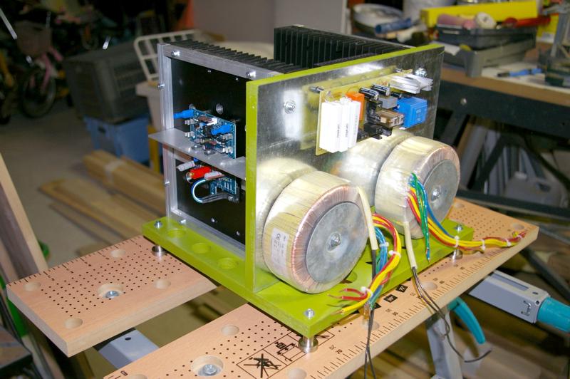
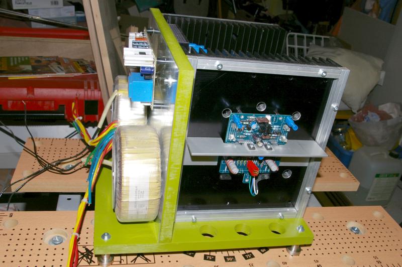
After wiring i have to complete casing.
Since I have Quasi building instructions, i am a little shy on VR2 Setting for first powering : What's the more accurate stting value / cursor value for VR2 to not apply a too high bias value at first turn on?
Marc
After wiring i have to complete casing.
Since I have Quasi building instructions, i am a little shy on VR2 Setting for first powering : What's the more accurate stting value / cursor value for VR2 to not apply a too high bias value at first turn on?
Marc
Member
Joined 2002
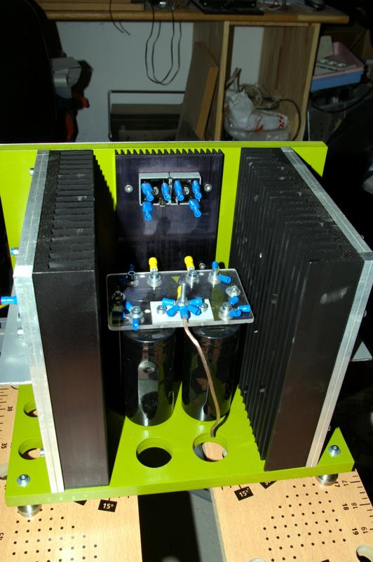
Thats a pretty big heat sink for those bridge rectifiers. Why not turn the heat sinks around and keep all your wiring on the inside. ?
- Home
- Amplifiers
- Solid State
- Power amp under development