Lateral Mosfets
What would be the changes if you changed the outputs of the NMOS 200 to laterals such as the BUZ900 and ALFET devices?
sam
What would be the changes if you changed the outputs of the NMOS 200 to laterals such as the BUZ900 and ALFET devices?
sam
Anyone selling a board for the NMOS200 with TO247.
sam
Here's the layout that I've used. Note that the track side is mirrored.
Hari
Attachments
Here's the layout that I've used. Note that the track side is mirrored.
Hari
Hi Hari!🙄
Have you mesaured the output watts of this PCB 2 pair TO247 package version?
Diyers welcomes your modification😀
personaly i like some thick tracks like quasi's PCB design.
Thanks
vijay
Hi Hari!🙄
Have you mesaured the output watts of this PCB 2 pair TO247 package version?
Diyers welcomes your modification😀
personaly i like some thick tracks like quasi's PCB design.
Thanks
vijay
I've not actually measured the output (like with a power meter or something like that). But it's atleast 150W into 8 ohms. I'm using +/- 60VDC supply.
As for track width, you will notice that I've used the widest possible polygon planes for the power, ground and the output tracks. These are more than adequate for this power.
One final word about Quasi's amp design - simply incredible😀. The clarity of the sound is amazing!!
I'm right now working on different variations of layouts for two and three pairs of TO247/TO220 etc. I'll keep posting them as and when I finish.
Hari
viki_v2, here's the gerber files (zipped). check them out and let me know if they're ok.
Hari
Viki_v2, please ignore the gerber files that I posted. The layout had some mistakes in it. I'm making the corrections now, will post the files later.
Hari
VI limiter for nmos amp you can see here
http://www.diyaudio.com/forums/solid-state/162494-amplifier-motherboard-5.html
Schematic of ARCAM ALPHA 10
Regards
have changed VI Limiter in NMOS like ARCAM ALPHA 10
could this work in NMOS with +/- 80V Rail ?
Attachments
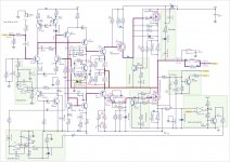
I suggest you to use output stage like ARCAM, with voltage gain just reduce to x1,5 (change R12,R13) and Bootstrap, you get more power with same rail voltage.have changed VI Limiter in NMOS like ARCAM ALPHA 10
could this work in NMOS with +/- 80V Rail ?
Regards
it seems that this thread has been gone to another way ...
just to remind that all the above is obviously thread jacking ...( that of course is neither my bussines nor my problem ) but just now that i like to place a question that is related to the quasi amplifier i think it will really look hat it come from the moon ....
any way
in the original QUasi amplifier as described in the first post there is a 27K resistor from the base of the Q5 BF469 to ground
can somebody describe the function of the specific resitor???
thank you
in the original QUasi amplifier as described in the first post there is a 27K resistor from the base of the Q5 BF469 to ground
can somebody describe the function of the specific resitor???
that res provides a current to bias the 2 diodes for the two currents sources.
So the 2 diode drops minus Vbe leaves ~ Vdiode/Rcs > for each current source
0.65/220 ~ 3 mA
0.65/39 ~ 17mA
Last edited:
ok then ...got it ... but here is another question ...in the schematic it shows that this one is conected to 0v of the main power supply ...and not the "clean" ground provide by the 10R resistor ...
I presume that since this provide current reference it is no more than reasonable to be connected on the power supply ground
correct ???
I presume that since this provide current reference it is no more than reasonable to be connected on the power supply ground
correct ???
Since the PS neg rail is the bottom reference, the pos current "gnd" should reference back to the supply gnd.
It may be better to tie it to the positive rail to cancel some PS ripple effect.
It may be better to tie it to the positive rail to cancel some PS ripple effect.
Last edited:
ok ...makes sense ..thank you ....and a fianal question ...
i have seen in some designs that these 2 diodes are bypassed by one capacitor do you know why and if an approach like that will ofer something more ???
thank you
i have seen in some designs that these 2 diodes are bypassed by one capacitor do you know why and if an approach like that will ofer something more ???
thank you
I dont think so, because the current source is from a diode drop and not derived from a PS reference.
Last edited:
Hello everybody. Already got one nmos running in my powered monitor.
I'm wondering if anybody had built Actrk nmos amplifiers with additional +rail.
Any opinions?
Also wondering if there is any different PCB with FETs mounted directly to heatsink, not by PCB-i'd like to experiment with number of fets ands different powers.
Any suggestions, PCBs or info would be helpfull(next month i'm attempting to make 2x 600W+2x400W All'in'one amplifier for SUBs and Sattelites)
thanx
Adam
PS Looking for something like pCB for NBIP300 but for actrk 600/400 with IRFP
Hi adam!
Nice to hear that again thread started to work on pcb and not on a paper(theoritical talks bla bla bla..😀) i have few pcb layout which have been posted by diyer on this thread. please check the layout througly with orginal schematic.
for more mosfet upgrade the driver mje 340/350 to mje 15003/15004. better ask quasi🙄
whises to sucess you project
Vijay Daniel 🙂
Attachments
Hi adam!
Nice to hear that again thread started to work on pcb and not on a paper(theoritical talks bla bla bla..😀) i have few pcb layout which have been posted by diyer on this thread. please check the layout througly with orginal schematic.
for more mosfet upgrade the driver mje 340/350 to mje 15003/15004. better ask quasi🙄
whises to sucess you project
Vijay Daniel 🙂
MJE15034 and 15035 works perfect and 2SA1837 / 2SC 4793 too in my NMOS you can use for VAS too working in my nmos
- Home
- Amplifiers
- Solid State
- Power amp under development