2n3055 used instead in quasi's bjt amp design
Hi all is there anything stopping me using 2n3055's in quasi's amp design for bjt's I notice he has used 2n3773 but the reason i would like to do it is i have lots of them lying around and i would like to use them in a amp. I would also like to know if rather than using 8 if i could use more like even 16 to get more power on a lower voltage power rail as the 2n3055 will only handle about 40 to about 58 volt power rails as far as i understand but i was thinking if you keep just adding them in the same fashion as quasi has on the output stages does this keep increasing your power good way to use those old 2n3055 up on a bang for buck amplifier.
Hi all is there anything stopping me using 2n3055's in quasi's amp design for bjt's I notice he has used 2n3773 but the reason i would like to do it is i have lots of them lying around and i would like to use them in a amp. I would also like to know if rather than using 8 if i could use more like even 16 to get more power on a lower voltage power rail as the 2n3055 will only handle about 40 to about 58 volt power rails as far as i understand but i was thinking if you keep just adding them in the same fashion as quasi has on the output stages does this keep increasing your power good way to use those old 2n3055 up on a bang for buck amplifier.
Hi,
you can get many different 2n3055.
By different manufacturers and different processes.
A sensible maximum of +-40Vdc for supply rails will give good reliability with genuine parts. You can use a little more with some higher voltage parts, but how do you know what you have lying around?
Moderate reactance 8ohms speakers on +-40Vdc can be driven with just one pair of 3055, but I would tend to use 2pair for 8ohm duty and 3pair for 4ohm duty. Stereo uses up 12 devices for a pair of 4 ohm speakers.
Each of the 4 sets of 3pair must be matched at the operating quiescent current you intend to use.
If you go for more parallel pairs, eg. 6pair output stage, then all 6 devices must be matched at your operating current.
Pecor 2n3055
Hi,
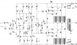
Thanks for your responce. They are pecor 2n3055 i have about 20 or of them. Is there anyway to force the transistor to be matched. via resistor as these amps will not be used for fidelity they will be used for more so PA type work. So fidelity is not as important as power is so thats why i was trying to add more. (mind my naivity here to learn thanks for your patience.) I read the schematic as four npn transistors in parallel at the top and four parallel npn transistors below in parallel which ones are they pairs?. I am hoping i can use them up for an amp that will do the job for not a lot of money thats pretty much what iam up to. Thanks
Hi,
4 NPNs for the top half and 4 NPNs for the bottom half make a 4pair quasi complementary output stage.
The 4 NPNs in the top half must be matched to each other. The 4 emitter resistors also need to be matched 5% or 10% is too wide a tolerance. Try for <2% and even better if you can get <0.5%.
The 4 NPNs in the bottom half also need to be matched to each other.
To build two channels you will need 16 out of your 20 device stock.
You need to find 4 sets of 4matched, that match in the sets, not between the sets. Test/measure Vbe @ your intended quiescent Ic.
Because the 3055 are low voltage devices you can never get big power from them. You are limited to ~+-40Vdc and this will give ~120W into 4ohms.
Hi Andrew,
Since you are mentioning 'emitter resistor matching', how do you go about doing that. DVM are useless (as least my $20 DVM is) in measuring under 1ohm range, right? I heard about wheatstone bridge (and of course encountered it some 30 years ago in my physics lab) but I still don't know how to do the matching. Tks for enlightment.
Since you are mentioning 'emitter resistor matching', how do you go about doing that. DVM are useless (as least my $20 DVM is) in measuring under 1ohm range, right? I heard about wheatstone bridge (and of course encountered it some 30 years ago in my physics lab) but I still don't know how to do the matching. Tks for enlightment.
Hi Andrew,
Since you are mentioning 'emitter resistor matching', how do you go about doing that. DVM are useless (as least my $20 DVM is) in measuring under 1ohm range, right? I heard about wheatstone bridge (and of course encountered it some 30 years ago in my physics lab) but I still don't know how to do the matching. Tks for enlightment.
you can rig up a 1 ampere constant current source out of an lm317, then you can measure the voltage across the resistor under test......
a 0.33 ohm resistor will drop 330 millivolts, easily measured thru a dmm....
reduce the CCS current so that ~199.1mVdc are dropped across each resistor to be measured/compared/tested.
If you string 10 resistors in series then you will drop ~2V across the whole string and you can measure the voltage across each. Matching to 0.1mVdc gives <0.05%. If you get an apparent 0.0mVdc with both reading 199.2mVdc then your matching is approaching 0.03%.
<0.5% requires voltages closer than 0.9mVdc in readings of ~199mVdc. EASY as pie.
And we have not even used the Wheatstone Bridge yet!
this schematic and many others are in the datasheet.
Just one lm317 and one current setting resistor are needed. The resistor is across adj and out.
The CCS output is taken from adj instead of the usual out.
CCS current is ~1.25/R, eg 20r gives 1.25/20 = 0.0625 = ~62mA.
62mA through a 2r7 resistor gives a Vdrop ~169mVdc
Just one lm317 and one current setting resistor are needed. The resistor is across adj and out.
The CCS output is taken from adj instead of the usual out.
CCS current is ~1.25/R, eg 20r gives 1.25/20 = 0.0625 = ~62mA.
62mA through a 2r7 resistor gives a Vdrop ~169mVdc
Kindly sketch a lm317 constant current source schematic ? Tks
page 18, LM317 - 3-Terminal Adjustable Regulator
you need a precision 1.2 ohm resistor rated 2 watts or better since that resistor will dissipate 1.2 watts.....voltage source can be anywhere between 2.5 to 5 volts......
a good source will be the pc's atx psu, you can tap the 3.3 volt rails...
putting a heatsink on the 317 will be a good idea...
using 1amp as reference current will give you a direct reading sub-ohm meter...
commercial sub-ohm meters works on this principle anyway...
have fun.....😀
Hi Tony,
If I am just using this constant current source to match the resistors in which I just need to measure the 'drift' from a certain norminal value, I would not have to get a very precise 1.2ohm, right? But of course if I am trying to measure the exact R value, then I do need that precise 1.2ohm, right?
BTW, I still have the boards and insulation pads with me.
use a combination of Wheatstone Bridge and serial connected resistors.
string 10 approximately equal but unknown value resistors together. If they are ~1r24, then the string will be ~12r4
Now attach that string to a measuring bridge. The bridge will need three 0.1% accuracy resistors if you want that order of accuracy in measuring your 1r2xx resistors.
Using 1% resistors in the bridge is OK, but first you must select matched resistors to reduce error margin.
Three suitable resistors for the bridge would be 1k0, 100r, 100r and a low value variable resistor. You need to be able to measure the final value of this VR to 1%. Better still if you have 4 matched 100r resistors. Two in parallel give ~50r and two in series give ~200r, but much more important the ratio of ~200:~50 is exactly 4.0000:1
Last edited:
IRF1310N compatibility
Hi all,
I have a few IRF1310N from international rectifier. What i can't work out is can i use them instead of the IRF452 or IRFP450 or IRF840 is the voltage the main difference with these mosfets. I would like to use the IRF1310N chips up if possible. The other question i had. I was talking to a friend of mine and they said that you could use a large bi-polar capacitor on the output of most amplifiers so that you don't destroy your speakers with stray dc current. But which is better a large bipolar capacitor of about 1000uf or a dc detect circuit. sometimes just when you think you know whats going on someone throws a spanner in to the equation curious on everyones thoughts and comments? Thanks
1. use a crowbar, its cost effective and save to protect your speakers
2. use electronic turn on delay fast/off to prevent switch on plop
2. use electronic turn on delay fast/off to prevent switch on plop
Hi all,
Where do i find a decent crowbar schematic and pcb layout thanks
http://www.diyaudio.com/forums/solid-state/164093-100w-ultimate-fidelity-amplifier-37.html
Post #368
Regards
hi qsa,nobody interested
to add supporting 2 Step Class H for NMOS +/- 140 V +/- 70 V
or +/- 40 and +/- 80 V ???
you have done so far regarding nmos,
quasi's design said from german(siemens),design now back to geraman guy🙂
congratulation,
regarding nmos + class h,that would be great,
thumbs up for that
keep up the good work
- Home
- Amplifiers
- Solid State
- Power amp under development