by ASKA - As you increase the rail voltage of a bipolar supply SS amp, the stability parameters change. To maintain stability you must revisit the compensation, that is, the 39pF cap across the base/emitter of the voltage amplifier must be increased.
To a small degree this is true , BUT ... would this not happen as the rails collapsed upon shutdown ?? I did a simulation and found a quasi-type amp will plot differently at 30 - 70 volt rails , but not to the point of instability.
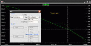
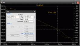
(Plot 1) is at 70 volts (base design) .. at 30 volt rails (plot 2) ,the unity gain point decreases by 100k and the phase margin is 10 degrees shy from original.
This still would not create a burning amp . Instead of changing cdom , I was able to clone the 70 volt plot by simply decreasing Re (more gain) on the active VAS tranny. To change Cdom will alter the sonics of the amp.
The sims showed that CDOM would have to be INCREASED at lower rails to maintain the same margin. (68 to 90 pf to get 95-98 degrees at 30 v)
I have built this type amp and have found it will work between 35 and 70volts , best at the voltage it was "tweaked for" ,even as the rails collapse down below 20V , the music still plays with no hint of instability until the output clips in response to insufficient supply voltage.
OS
Attachments
Last edited:
Hugh, I have a schematic of my exact version done in DipTrace. When I get to my office I will try to export this to MS Paint and then send it to you.
OS, you are right. My working amp has very stiff rails of 63volts. The one that is giving me a headache was tried at 42 volts and 56 volts. Reducing Re on the active Vas only might solve the problem but the sonics are not as good when the resistor value is not the same on the corresponding current source. Increasing Cdom will also kill the sonics to some extent.
You do have a valid point on collapsing rails.
From all your sims I have seen so far, you have a Red LED (voltage drop?) to fix the base of the current source transistor but Quasi has used 2 diodes. Somewhere in the thread it was reported that a Yellow LED works well for lower rails. I have tried it but the current draw is too much.
Also in your sims, for the Quasi type input stage, would it not be better to insert a resistor into the base of the current source for the Vas?
I use Electronic Workbench for simulation but you use LT Spice. Does the current draw vary according to the setting of the trimpot in Vbe multiplier? In my sims the current draw drops to zero for some values of the trimpot whereas in the non-working practical circuit the current draw shoots through the roof and burns up the 10E resistors I use in the rails for testing.
Sam,
Do please send it... I have schemats here of the NMOS400, but we need to be on the same page.
As you decrease the rail voltage, you should ensure all LTP and VAS currents are the same. I've generally found you should then reduce Cdom, but if OS has found otherwise, so be it.
I use LTSpice so my results may not precisely correspond to yours since models may be different, even phase margin results may differ.
Cheers,
Hugh
To a small degree this is true , BUT ... would this not happen as the rails collapsed upon shutdown ?? I did a simulation and found a quasi-type amp will plot differently at 30 - 70 volt rails , but not to the point of instability.
(Plot 1) is at 70 volts (base design) .. at 30 volt rails (plot 2) ,the unity gain point decreases by 100k and the phase margin is 10 degrees shy from original.
This still would not create a burning amp . Instead of changing cdom , I was able to clone the 70 volt plot by simply decreasing Re (more gain) on the active VAS tranny. To change Cdom will alter the sonics of the amp.
The sims showed that CDOM would have to be INCREASED at lower rails to maintain the same margin. (68 to 90 pf to get 95-98 degrees at 30 v)
I have built this type amp and have found it will work between 35 and 70volts , best at the voltage it was "tweaked for" ,even as the rails collapse down below 20V , the music still plays with no hint of instability until the output clips in response to insufficient supply voltage.
OS
The ~10 degrees variation shown in your sim is pretty negligible in this context. The amplifier’s phase margin will suffer much worse when driving any kind of realistic load.
To put it another way, for the amplifier to suddenly become unstable on either half or double the rail voltage, it would have to be very poorly designed with a hardly adequate phase margin in the first place.
The problem is likely elsewhere.
Last edited:
By samual - Does the current draw vary according to the setting of the trimpot in Vbe multiplier?
NOPE , not on ANY of the amps I have used the red LED CCS's. A very small deviation can be seen as a amp is monitored at shutdown (20V and down).
Using the 340/350 pair a little more spread can be seen , but less than .1ma.
Hugh, on a non -current sourced LTP (RCA-bootstrapped) ,the compensation may go the way that you predicted. Most likely this is the local feedback loop of the bootstrap.
I have built both the IRF version of the quasi and the "brother" (BJT-above) , and tried both fairchild semi's and the 340/50's. My compensations are slightly different , but this design has a very wide margin , and remains stable with any layout. Makes for a good sub amp. 🙂
On all my CCS's , I just change the Re's on the main CCS (300r= 1.7ma LTP , 330r= 1.5 , etc) and on the VAS CCS (100r = 10ma , 150r= 7.2ma).By samual - Somewhere in the thread it was reported that a Yellow LED works well for lower rails. I have tried it but the current draw is too much.
OS
Last edited:
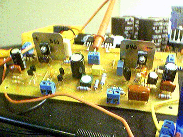
Referring to OS schema presented in another thread, which is essentially Quasi's input stage, my circuit has the following component values changed:
R8, R9=330E, R7=33E, C3=330pF, R5, R4=150E, R14=220E, R12, R13=12K, C5=33uF, R2, R11=33K, R15, R16=56E, Q3, Q4=BC556B, Q5=BC546B, Q6=2SA1593, Q8=KSE340
Other than a couple of parts, Quasi's original components and values have been retained. Between LTP Re and CCS is a 10K resistor and in place of the CCS LED are 2 x IN4148 diodes.
GK might have a point. I am also suspecting stray capacitance due to copper-fill in the troublesome PCB while the working one was plain vanilla.
However, I'll check again and report any more new findings. My interest in this is not only to get a stable working amp, but to investigate with the help of all you knowledgeable folk whether this generic topology popularised by Douglas Self is worth pursuing any more at all, both in terms of stability and sonic quality.
Attachments
![self[2].gif](/community/data/attachments/142/142879-90e26756e84494794ae1fb95dd333c87.jpg?hash=kOJnVuhElH)
hi guys dose any one know the scematic for the qasis nchan mos500
ISO-8859-1__nchan mos500 with dc detect v1-1 layout.pdf
Download ISO-8859-1__nchan mos500 with dc detect v1-1 layout.pdf from Sendspace.com - send big files the easy way this is pdf layout
Download ISO-8859-1__nchan mos500 with dc detect v1-1 tracks.pdf from Sendspace.com - send big files the easy way this is pdf for tracks
i already made the pcb and the data related to this pcb was corrupted on my PC
Please help me ....
hi guys dose any one know the scematic for the qasis nchan mos500
ISO-8859-1__nchan mos500 with dc detect v1-1 layout.pdf
Download ISO-8859-1__nchan mos500 with dc detect v1-1 layout.pdf from Sendspace.com - send big files the easy way this is pdf layout
Download ISO-8859-1__nchan mos500 with dc detect v1-1 tracks.pdf from Sendspace.com - send big files the easy way this is pdf for tracks
i already made the pcb and the data related to this pcb was corrupted on my PC
Please help me ....
hi ary5678
check out the quasi main site
Quasi's DIY Audio
ravs
be a vegeterian.......
Thanks for the replay ravslanka And AndrewT ;
i checked the quasi's site but the scematic and the layout are diffrant than the PCB i made; afterwords i knew that the PCB i made was the same layout & tracks of Actrk400 but with 10FETS and DC Detect , so the problem now solved , i made the wrong PCB , i had to to made that RAIL+10V PCB , i ll do it next time , nywayz Thanks for the support....
i checked the quasi's site but the scematic and the layout are diffrant than the PCB i made; afterwords i knew that the PCB i made was the same layout & tracks of Actrk400 but with 10FETS and DC Detect , so the problem now solved , i made the wrong PCB , i had to to made that RAIL+10V PCB , i ll do it next time , nywayz Thanks for the support....
Hi,
I am new to this thread and I want to build the NMOS500. Is there already a pcb for NMOS350 MKII? I have seen the specs of IRFP450 & IRFP460 and with the small diference in price it is economical to use the 460. the IRFP460 has different variations as to Id the original with 20A and there is the 32A & 36A but the price is to stiff. Can I have some advice on this?
I am new to this thread and I want to build the NMOS500. Is there already a pcb for NMOS350 MKII? I have seen the specs of IRFP450 & IRFP460 and with the small diference in price it is economical to use the 460. the IRFP460 has different variations as to Id the original with 20A and there is the 32A & 36A but the price is to stiff. Can I have some advice on this?
Web Site Moved
Greetings,
I changed ISP's recently and had to quickly move my web site. It is located here; Home (Quasi's DIY Audio Site)
It is re-built so please be patient.
Cheers
Quasi
Greetings,
I changed ISP's recently and had to quickly move my web site. It is located here; Home (Quasi's DIY Audio Site)
It is re-built so please be patient.
Cheers
Quasi
ok, i have spent the better part of a day trying to figure out how to describe this problem, so bear with me.
I have built the NMOS 500 version of this amplifier (there is a schematic on this thread somewhere, its also on Quasi's web site). The issue is, when the amplifier is loaded up with 4 ohm speakers bizarre things happen.
Bizarre is hard to explain. There is a huge amount of distortion present on both the input AND the output, sometimes the distortion gets so bad that it causes the DC detection circuit to turn the speakers off momentarily. It has been proven that this distortion is not coming from any device before the NMOS500, but is being introduced by the amplifier itself.
To say again, this only ever happens when the amplifier is driving a 6ohm load or less. Distortion being colouration of the sound (or test tone) with some sort of harmonics, and also a distinct poping sound every few seconds.
The issue is either the NMOS500 becomes unstable under heavy loads, or there is some interference (crossover distortion?) being introduced through the power supply to the amplifier. Any ideas would be very much appreciated. Even a hint as to where I should be looking would be helpful.
If anyone needs/wants any measurements just let me know. Cheers and thanks.
-canca87
Hi,
short the input. Leave the output open circuit and check the AC and DC output voltages.
Connect a 4r0 reistor load with the input still shorted.
Check the AC and DC voltages at the output.
Connect your source but with volume at zero.
Check the AC and DC output voltages.
Apply a low level signal with the output open circuit. Check that the amplifier gain is about right, i.e. Output AC volts ~ amp Gain * input AC volts.
Now connect a 4r0 resistor load and check the amp gain again.
some measurements:
input shorted, output open, AC=0.005v, DC=0.000v.
input shorted, output 4r0, AC=0.005v, DC=-0.001v.
input source (no volume), output 4r0, AC=0.005v, DC=-0.003v
input source (low volume), output 4r0, AC=0.718, DC=+0.005v
gain was difficult to calculate as the distortion is present even at very low volumes (i use a CRO to take measurements for gain). gain = out/in = 2.1v/0.065v = 32.3
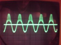
the gain of the amp is about right (with room for error, my method for measuring is not very accurate). A description of the distortion, its only on the positive peak of a 440Hz sine wave. Another interesting note, the distortion is present on the input waveform too. When the signal generator is not connected the sin wave looks pure, when it connected to the amplifier the distortion is obvious on both the input and the output waveforms.
hope that helps. thanks
-canca87
input shorted, output open, AC=0.005v, DC=0.000v.
input shorted, output 4r0, AC=0.005v, DC=-0.001v.
input source (no volume), output 4r0, AC=0.005v, DC=-0.003v
input source (low volume), output 4r0, AC=0.718, DC=+0.005v
gain was difficult to calculate as the distortion is present even at very low volumes (i use a CRO to take measurements for gain). gain = out/in = 2.1v/0.065v = 32.3
the gain of the amp is about right (with room for error, my method for measuring is not very accurate). A description of the distortion, its only on the positive peak of a 440Hz sine wave. Another interesting note, the distortion is present on the input waveform too. When the signal generator is not connected the sin wave looks pure, when it connected to the amplifier the distortion is obvious on both the input and the output waveforms.
hope that helps. thanks
-canca87
Hey Quasi Thanks for the Amp .... That's a gr8 amp Crystal Clear Output at very high volumes on full ranges ,
Even I used as sub-woofer amp in active sub-woofer--- Very high punch
Good er than the Sunfire Sub !
i used a "Reflex Audios (RFX)" 10 inch 1000W Max Driver *(Designed by me and) about 900W RMS Sub woofer And transformer is 1250 VA its almost giving me 850WRms @ 2 Ohm 5 FETS the Sub Is 450WRms x 2 @ 4 Ohm
The Base Is Killer ! Thanks Again.....
That looks really wierd, and definately oscillation. Is everything grounded ok including the heatsinks. Is the input ground secure?
I've driven an Nmos350 into 4 ohms cleanly (the Nmos500 shoul be no different).
What DC rails do you have ?
Cheers
Quasi
I've driven an Nmos350 into 4 ohms cleanly (the Nmos500 shoul be no different).
What DC rails do you have ?
Cheers
Quasi
I have been triple checking all my ground connections. But it all seems to be solid, including input ground. I am using DC rails of +/-70V (but under no load the voltages sit at about +/-77V).
I have tried increasing C4 (VAS capacitor) to values as high as 330pF, but still no luck. I am using your board design for the amp so its not a problem with the layout.
thanks, -canca87
I have tried increasing C4 (VAS capacitor) to values as high as 330pF, but still no luck. I am using your board design for the amp so its not a problem with the layout.
thanks, -canca87
- Home
- Amplifiers
- Solid State
- Power amp under development