I have been reading up about amplifiers and how they are rather unstable when driving capacitive loads (even slightly capacitive ones). This got me thinking, maybe the crossovers in some speakers are causing the amplifier to see a slightly capacitive load (any my test load may be slightly capacitive).
When a square wave input was applied to an amp driving these particular speakers, I used the CRO to monitor the output. The CRO showed the typical high order ringing on the output when a square wave source was applied. When the amplifier is driven a little harder the ringing turns into oscillation.
So I tried an inductor in series with the load, its only a small 1.6uH inductor. Now the oscillations are orders of magnitude smaller. They are still present but defiantly not as significant or damaging.
Is this any hint as to what the issue could be? any comments on that?
Electronic turn on delay in NMOS
I dont like relay, could this Electronic turn on/off delay in NMOS work or is it faulty ?
attachment: schematic
When +12V DC is supplied from T23/BC879 to D1, T1/MPSA92 turns on and charge C3 through R4. After this short delay T4/MPSA42 turns on and the amplifier operates normally. When T4/MPSA42 is off, the amplifier will not pass signal; the output appears as a resistor to ground
Attachments
...maybe the crossovers in some speakers are causing the amplifier to see a slightly capacitive load
...
So I tried an inductor in series with the load, its only a small 1.6uH inductor. Now the oscillations are orders of magnitude smaller. They are still present but defiantly not as significant or damaging.
Is this any hint as to what the issue could be? any comments on that?
What you are describing is a capacitance isolation network, often called a Zobel or Boucherot cell (in fact the whole network is really both of those together) - commonly seen at the output of many amps. The inductor should have a small value resistor across it (about 4-10 ohms), to prevent a purely capacitive load becoming a tuned circuit with the series inductance, in theory being a short at their resonant frequency.
The inductor actually 'siolates' the capacitive load from the amp by increasing it's impedance at higher frequencies, corresponding to the fast rise times of the squarewave edges.
However, at these same frequencies, the amp then sees less, and even no load. This is why there is usually a resistor approx. the vaule of the nominal load in series with a capacitor at the output of the amp, before the inductor - this takes the part of the laod that the inductor has 'isolated'.
As to the reasons for the overshoot/ringing - there could be many, starting from a resonant circuit being formed between the load and amplifier output impedances, to adverse effects of feedback used in the amplifier. With the latter, it indicates the inability of the (usually) output stage to drive the output signal as fast as the (input signal * amplification factor) would require, resulting in the feedback network overcompensating once the fast part of the signal is over (eg. the edges of a squarewave). The reasons, implications and possible solutions for this are WAY beyond the scope of this topic.
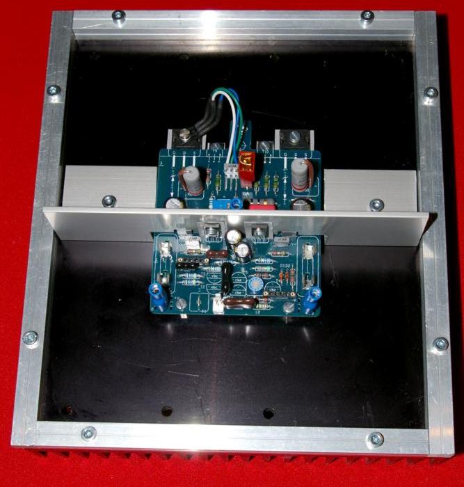
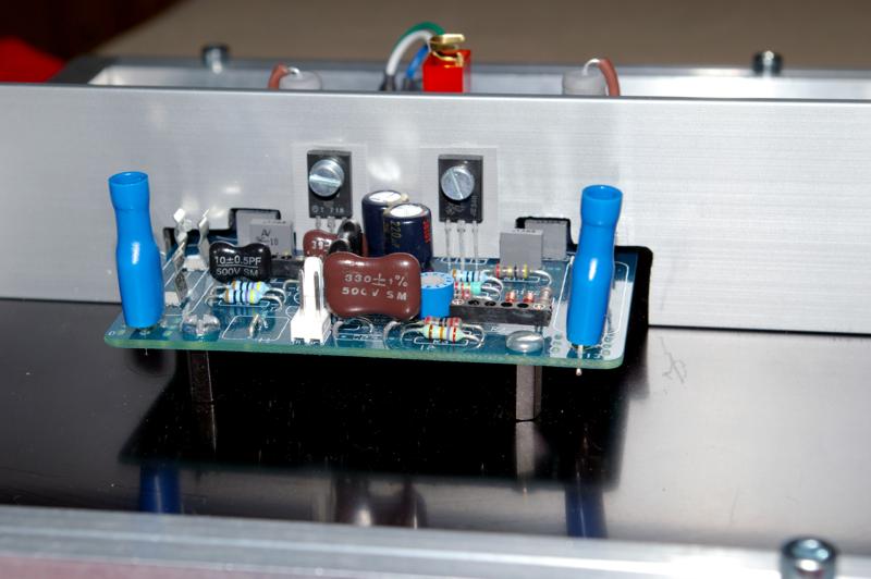
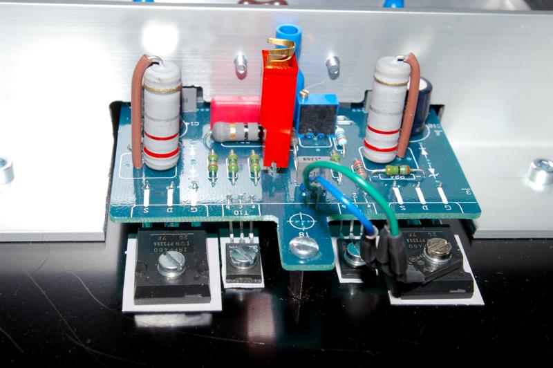
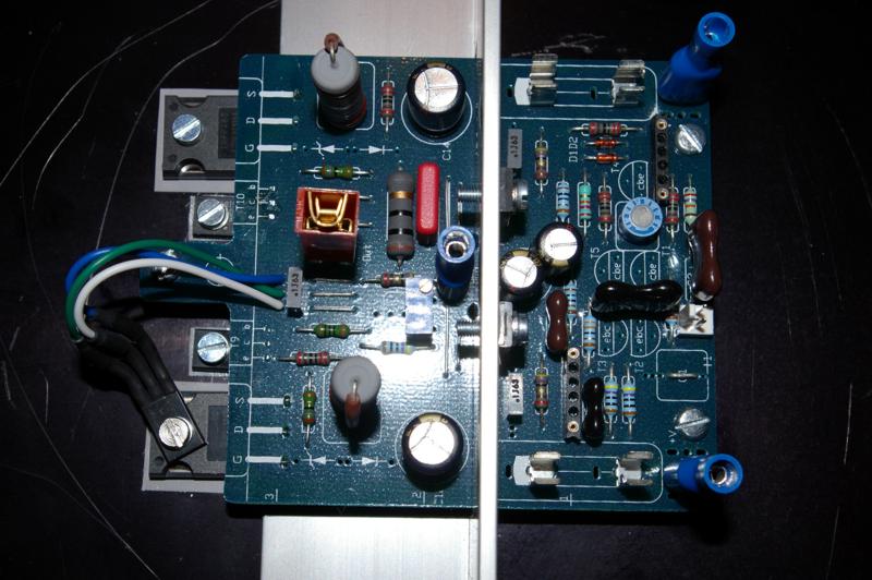
Some month ago i pick a couple of nmos200 from a another diyhobbist through an output device exchange. Last couple of week i purchase the lefting parts to completing and mount the amplifier. The whole mechanicals parts and PSU parts are recondionned ones (heatsink for exemple came from industrial rubbish, they are scratched and drilled but totaly useable. I use a couple of IRFP460 couple for output devices.
Here a few shoots from where i am in this project. I have to mesure small bipolaire transistors for matching...I will use veernered wood for casing with a alumium top.
Marc
Here a few shoots from where i am in this project. I have to mesure small bipolaire transistors for matching...I will use veernered wood for casing with a alumium top.
Marc
Last edited:
Member
Joined 2002
Thanks, I need to made same mechanical work for second chanel. Heatsink will be situated in the middle of the case and not viewable with closed case.
Marc
Marc
Member
Joined 2002
Thanks, I need to made same mechanical work for second chanel. Heatsink will be situated in the middle of the case and not viewable with closed case.
Marc
Right on, keep up the good work, keep us posted with some great photo's.
Jase
Today I have finished my first NMOS 350 and listen........
and Im shocked 🙂
NMOS is one of the best sounding CLASS AB amplifier, its not a joke its really TRUE
I can hear details in music what I did never heard before, amp is working very stable without thermal runaway, I want say... heatsink is about 30 degrees after 4 h listening
thank you
QUASI
for this great amp
merry X mas
Last edited:
pcb
Hi qsa I like this circuit also please send me copy off pcb drawing thanks .khalsaaudiocenter@yahoo.com
Hi qsa I like this circuit also please send me copy off pcb drawing thanks .khalsaaudiocenter@yahoo.com
Today morning have test again my NMOS sample..... Bass is deeper & rounder compare to commercial Class D and Class H amps...perfect for driving large subwoofers with definition and punch this makes it easy to fill a large club with sound without filling a rack full of amplifiers
@khalsa will send you tomorrow
if you want build please note: VI and crowbar DC Fault protection is very important, relays are to slow to protect speakers in catastrophic failure
cant understand HI-FI / High End audio people to engineering and sell amps without VI and DC Fault protection, defective commercial Amp destroyed my Infinity home speakers, since this time by me ..... no way to use my speaker without crowbar DC Fault protection
does somebody have idea to add balanced input in nmos ?
have ground loops noise from active crossover
Last edited:
against balance input to prevent earth loops and noise in nmos
have found this.... Figure 2 - Balanced Line Receiver
Balanced Line Driver & Receiver
Is it a good idea, does somebody test it ?
and I think we should replace TL071 with LME 49710 for better sound
have found this.... Figure 2 - Balanced Line Receiver
Balanced Line Driver & Receiver
Is it a good idea, does somebody test it ?
and I think we should replace TL071 with LME 49710 for better sound
Hi Marc,
What did you use for Q8? Did you modified any components to use it?
Tks
I use a MJE340 and modify nothing for moment
Marc
fig2 is not balanced.
The impedances on the two inputs are different.
do you have any idea how to solve this problem ?
regards
Peter
Member
Joined 2002
don't use a balancing input that is referenced to ground.do you have any idea how to solve this problem ?
> don't use a balancing input that is referenced to ground.
why not ? Im a little confused....I dont understand it
why not ? Im a little confused....I dont understand it
- Home
- Amplifiers
- Solid State
- Power amp under development