fig2 is not balanced.
The impedances on the two inputs are different.
The impedance seen by a common mode signal is the same on both inputs which is what matters. See Douglas Self (starts below figure 9):
Balanced Line Technology
power amp
hi qsa
greetings and best wishes for a happy new year .Happy to know
amplifier is working and sounds good want to know few things
1 power output in 4 ohms
2 can more output fets be added to increase power
3 any substitute for diodes HER204
4 any substitute for darlington transistor BC869 can BD681 be used
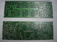
prototype pcb is ready single sided
please can you post picture of your prototype
any BOM wattage of resistances and zener diodes
thanking you
andrew lebon
hi qsa
greetings and best wishes for a happy new year .Happy to know
amplifier is working and sounds good want to know few things
1 power output in 4 ohms
2 can more output fets be added to increase power
3 any substitute for diodes HER204
4 any substitute for darlington transistor BC869 can BD681 be used
prototype pcb is ready single sided
please can you post picture of your prototype
any BOM wattage of resistances and zener diodes
thanking you
andrew lebon
pictures from professional NMOS PCB 220 x 80
pictures Heatsink and SMPS Power Board +/- 80V for NMOS
will build next days and send new pictures....
@andrewlebon
you can use BD681
HER204 is optional, dont know substitute
> power output in 4 ohms....can more output fets be added to increase power
with 100 V DC you can use 3 pcs. IXYS IXTK110N20L2
or 6 IRFP 460 Fets
Attachments

power amp
hi qsa
greetings nice pictures with 100 volts supply did you mean 6 pairs
what would the maximum output be in 4 ohms
thanking you
andrew lebon
hi qsa
greetings nice pictures with 100 volts supply did you mean 6 pairs
what would the maximum output be in 4 ohms
thanking you
andrew lebon
I think about 1000W RMS @ 4 OHM oder 2000W RMS BURST
actually have problem with another NMOS its original quasi schematic
cant find fault against big DC OUT failure about 60-80 V DC
1. all Mosfet,... T6 and T10 are removed now
2. Voltage @Base from T9 after Resistor R16 is about 80 V, DC out is about 67V DC
3. have remove resistor R16 from T9 and DC out failure is gone/solved
4. have checked resistor R19, there is about 80V DC too
have headache from NMOS does anybody have idea to solve this problem ?
hello, need a little help for nmos
have build second nmos but with catastrophic failure
at collector from T7 in quasi schematic from NMOS 350 is about 80V
In my another working nmos there is about 1,6 V at collector from T7
does anybody have idea to fix this problem ?
after remove R11 /27 K the 80V DC at collector from T7 is gone....im confused what to do now ?
How?I think about 1000W RMS @ 4 OHM oder 2000W RMS BURST
1000W into 4r0 requires 89.4Vpk and 22.4Apk.
2000W into 4r0 requires 126.5Vpk and 31.6Apk.
Each of these will need a power supply that is way above +-80Vdc
Hi Quasi
have - 80V DC at collector
I hope you can help me to solve this fault in PCB
after cant find fault in defective PCB have built today morning a new NMOS with my last PCB, .... is working since today afternoon
Im using in this new NMOS PCB for T6 and T7 2SB 649A/ 2SD 669A and for T9 and T10 2SA 940 / 2SC 2073
T2 and T3 MPSA92, T1 and T5 2SC 2240, T4 MPSA42
Sound is wonderful, amplifier is working very stable with +/- 80 V SMPS
Hi Quasi.
In nmos200 schematic c8 is a bipolar capacitor.In layout is a polarized one.That`s ok for my point of wiew.However c8 is inverse on layout?Is not better that the positive pole to be on resistor r19?
At startup it seems to be a fault.
Nmos200 (Quasi's DIY Audio Site)
In nmos200 schematic c8 is a bipolar capacitor.In layout is a polarized one.That`s ok for my point of wiew.However c8 is inverse on layout?Is not better that the positive pole to be on resistor r19?
At startup it seems to be a fault.
Nmos200 (Quasi's DIY Audio Site)

Hi Quasi.
In nmos200 schematic c8 is a bipolar capacitor.In layout is a polarized one.That`s ok for my point of wiew.However c8 is inverse on layout?Is not better that the positive pole to be on resistor r19?
At startup it seems to be a fault.
Nmos200 (Quasi's DIY Audio Site)
The DC voltage across this capacitor should be 0v i.e. the same as the DC offset on the output. It is possible that during startup a DC voltage could appear across this and I must admit I've never looked at the voltage during start up. If the voltage at the junction of C8 and R19 is positive during start up then the capacitor should be turned around. If you have your amp handy can you please measure this and report back. I will then make the change on the schematic and PCB.
Cheers and thanks for the information.
Quasi
Hi QUASI
TANKS for your splendid ampli this is my ultimate Nmos200 version.

This is my website with Nmos200 costruction step. link quasi Nmos200
Max67
Hi Max,
I see you have changed your web site. It looks very nice, as does your finished Nmos200 (with the LED) stereo amplifier. It is one of the nicest amp builds I have seen. Congratulations.
In comparison to the photo of you in the snow it is 43 degrees C here today so I am inside with air conditioning on full. It has been over 40 for 4 days now and it will be 43 again tomorrow.
I have seen the video's of the mini-CNC as well, you're quite clever Mr Max.
Cheers and have a great new year.
Quasi
Hello everybody, i've got problem with this amp. It's oscillating on RF, exactly all four MJE are oscillating. Exept this everything seems to be ok. but i can't make Voltage level to stop overheating and oscillating. Project is based on PCB from quasi's webpage, but i cut off one power fet (only 4 pairs of IRFP 250N)supply rails are +/-71VDC. Board is located on Alloy-magnesium plate , 4mm thick grounding is located to powers supply pcb, heatsinks are grounded. May it be cased by non symmetrical Hfe for Mje 340 (about 75) and Mje 350 (about 160)? I think it shouldn't oscillate even without metal case/chassis.
For any ideas i'll be grateful
For any ideas i'll be grateful
hi every body .... I am building the Nmoss 200 using Irf540n.....With a transformer of 25-0-25v 8amps ........ Is there any thing I should know in advance before powering up the amp... Any suggestion would mean a lot ,,,,,,,
Hi for the first time check DC Offset before connecting with speaker, if there is about 1 - 30 mv amplifier is working..... you can adjust DC Offset between 1 - 5 mv.... listen and enjoy....
I use my NMOS 350/500 with +/-80 V DC, NMOS working wonderful with great sound
Dont worry after first firework...
my
1. NMOS is working since today
second NMOS burning up after connect with +/- 80 V DC because catastrophic fault in PCB Design
After finished new PCB Design 3. NMOS working since today
Heatsinks from NMOS are cold after 5 h listening, NMOS working very stable
But my was burning 3 times already:/ DC offset is always checked and set exactly to 0.00level. Do You have any alternative, working PCB for NMOS? WHat about hot MJE 340/350? This is very strange, they're hot without any IRF, I had RF oscillation, but already used some C to block it,but still they are hot, especially strange becouse i added heatsink from PIII 500MHz...and its also very hot. I'm bored and sick from replacing this transistors (they aren't cheap). Also there's possibility of unmatched IRF but does anybody matched them?
Hi
> Do You have any alternative, working PCB for NMOS?
Yes I have double layer working NMOS PCB,
actually have finished latest NMOS PCB including VI Limiter, Electronic turn ON/OFF, this means we dont need Relay for turn ON/OFF and DC Protect
I dont do business its only for diy hobby but trust me, the NMOS sound is great in my opinion better than Class D amps
my first working NMOS has
MJE15034 and MJE15035 in VAS and Driver Stage
BD 139 for VBE
my second working NMOS has
2SD 649 /669 A in VAS
2SA1837 / 2SC4793 in Driver Stage
BD 139 for VBE
have replace all
BC 556/546 Transistor with MPSA 42 / 92
2SC 1845 Transistor with 2 SC 2240
Did you mean that i shoulew replace this bc to mps?i bought about 50 pcs sc 1845,it's rather difficult to find them.Are 2240 more suitable there? Can i replace this mje for newer type like yours?i think they are fake,just imitation of fairchild,especially in such differences in their hfe/beta.But i still dont know why they are overheating?maybe fake,maybe hfe,or smth else.
- Home
- Amplifiers
- Solid State
- Power amp under development