The if 12v 1W zeners tripped... It would-
1.burn out the mje340/350's ,
2.then blow the fuses.
3.But, save the more expensive outputs and the board
from destruction/ fire.
Mje340/50's are just 10 cents(cheap).
OS
1.burn out the mje340/350's ,
2.then blow the fuses.
3.But, save the more expensive outputs and the board
from destruction/ fire.
Mje340/50's are just 10 cents(cheap).
OS
Hi OS,
That's what they are there for, to trigger the lesser of the 2 evils, burning of the cheap drivers rather than the expensive fets and the pcb. So what I mentioned should be OK : 12v 1w (can it go 2w?) + 1n4002/4/7 (which should be best?)
Tks for the input.
That's what they are there for, to trigger the lesser of the 2 evils, burning of the cheap drivers rather than the expensive fets and the pcb. So what I mentioned should be OK : 12v 1w (can it go 2w?) + 1n4002/4/7 (which should be best?)
Tks for the input.
12V Zener + diode conducts @~12.6V
Look at the FET datasheet and see what peak current will flow when Vgs=12.6V.
I suggest a lower voltage Zener (7V to 10V) if you want effective protection.
Look at the FET datasheet and see what peak current will flow when Vgs=12.6V.
I suggest a lower voltage Zener (7V to 10V) if you want effective protection.
adrianvill said:Hey fellas..
about the Nmos200 from quasi,
How do you set the bias resistors VR1 and VR2 ?
hi adrianvill
biasing procrdure is the same for all nmos series amplifier except actrk400/600 here is the link
http://www.adam.com.au/cgpap/QuasiWeb/pdf's/Nmos%20350-500%20Construction%20Guide.pdf
30-35ma per output device (across rail resistors in place of fuses )
enjoy the amp mine is running for 5 months with no problem
thanks quasi for your designs and providing them for free
hi guys,i have started making the nmos 350 following the instructions given at the site http://www.adam.com.au/cgpap/QuasiWeb/index.htm. i want to ask about those diodes you reffered for protecting the output fets.where do i put this diodes?could someone give me the schematic and tell me exactly what are they used for??thanks a lot.by the way,how does the nmos 350 sounds?
If you include them you only burn diode and drivers in
catastrophy, but if you don't want to include them, go to post
3023 page 121 for worst case outcome...
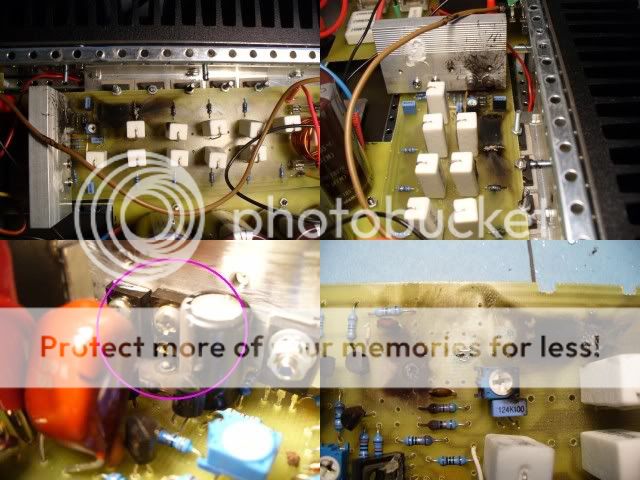
(The only disadvantage of "sandwich" style of board.)
the diode's prevent breakdown of gate which leads to a "wire"
where there used to be a FET.
Go to ...http://sound.westhost.com/project101.htm
delete zd2/d2 ,put another zd1/d1 combo between
-Ve and base of lower fet's..all set ..totally your choice..
OS
catastrophy, but if you don't want to include them, go to post
3023 page 121 for worst case outcome...
(The only disadvantage of "sandwich" style of board.)
the diode's prevent breakdown of gate which leads to a "wire"
where there used to be a FET.
Go to ...http://sound.westhost.com/project101.htm
delete zd2/d2 ,put another zd1/d1 combo between
-Ve and base of lower fet's..all set ..totally your choice..
OS

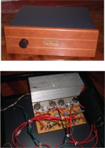
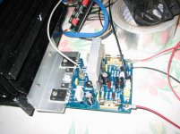
Finally finish the Nmos200 yesterday and listen for more than 5 hrs. The most difficult part is the drilling of the heatsink as usual. Calibration is smooth with no surprise, fortunately. It sounds as nice as the AV400 that I had before but with much lower count of components. Must try out the higher power or BJT version next year.
Attachments

well done.i am finishing nmos350 these days...hope it sounds good with no problems come up later.... im thinking of putting the protection zeners discussed earlier.i bought 7.5 volt 11 volt and 12 volt zeners capable of handling 3-5 amperes, but i dont know which ones to use....any suggestion?:
Hi,
look up the Vgs v Id curves for your FETs.
What current will the FET pass with a 7.5V Zener and a 0.6V diode in series between gate and source?
If the Zener is taken to the output end of the source resistor instead of the Source, you can engineer in a slight slope to the I protection limit.
If the output current is in phase with the output voltage (resistive load) then max current occurs when Vds is low and thus lowish dissipation until the fuses blow. eg. when a short on the speaker leads happens.
If the load is reactive then the current can be out of phase with the voltage and now Vds can be high and output current can be medium, but the dissipated power can be very high. This is the condition that really stresses the FET's SOAR. Fuses cannot prevent damage in this situation, they are too slow. The current limiter alone provides the protection. This is now when the lower voltage Zeners become really useful.
hi .i am using 4 irfp460 ,i have complited my board and now i m waiting for the transformer to power up my nmos350.
to quasi:
whats the THD of your nmos350? my board is complited based to the parts for sale for nmos350 and the schematics of your site.
http://www.adam.com.au/cgpap/QuasiWeb/index.htm
are there any updates since then that i should consider for nmos350??
thanks🙂
to quasi:
whats the THD of your nmos350? my board is complited based to the parts for sale for nmos350 and the schematics of your site.
http://www.adam.com.au/cgpap/QuasiWeb/index.htm
are there any updates since then that i should consider for nmos350??
thanks🙂
- Home
- Amplifiers
- Solid State
- Power amp under development