ostripper said:Hey, Quasi ..why no cascodes on LTP and why did you choose to use current mirror instead???
One of the development phases of this amp included a cascoded 1st stage http://www.diyaudio.com/forums/showthread.php?postid=498696#post498696 but I don't like cascoded stages so I changed it in post http://www.diyaudio.com/forums/showthread.php?postid=540840#post540840 where I give some of my reasons.
Cheers
Q
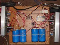
Ok, finally at the last stage here. ALL DIY custom Qausi.
First the layout....
Then the paint(No etchant undercut)..
Finished product w/thick rail traces..
Topside layout (seperate VAS as qausi recommended/
outboard Zoble/red LED..etc.)
\
And finally 2 dumpster 500va 45-0-45 w/24v extra sec.
10-1-08 I can listen to my first Mosfet amp
and say good riddance
to stupid walmart chipamps(give it to my daughter),
thanks for answering so many stupid ???'s.., I,m sure I'll have
more!!
First the layout....
An externally hosted image should be here but it was not working when we last tested it.
Then the paint(No etchant undercut)..
An externally hosted image should be here but it was not working when we last tested it.
Finished product w/thick rail traces..
An externally hosted image should be here but it was not working when we last tested it.
Topside layout (seperate VAS as qausi recommended/
outboard Zoble/red LED..etc.)
\
An externally hosted image should be here but it was not working when we last tested it.
And finally 2 dumpster 500va 45-0-45 w/24v extra sec.
An externally hosted image should be here but it was not working when we last tested it.
10-1-08 I can listen to my first Mosfet amp
and say good riddance
to stupid walmart chipamps(give it to my daughter),
thanks for answering so many stupid ???'s.., I,m sure I'll have
more!!
Hi Quasi,
I will check it with my vendor today and let you know its price if he has!!
Regards
I will check it with my vendor today and let you know its price if he has!!
Regards
Hi Dear Quasi,
Can you tell me some online electronic store in Australia where I can shop online?
Regards
Can you tell me some online electronic store in Australia where I can shop online?
Regards
Hi all. I have built this amp riecently (will post some pics) however im having troube getting the DC detect circuit to work. Im using Quasi's NMOS500 layout, but the dam relay wont click over. I figured it could be some transistor not working right, so ive changed a few but not improvement.
taken some Vce measurements if it helps: (im using a 16v source, but a 24v source doesnt work either)
Q1: 0v, Q2: 0.5v, Q3: 0.5v, Q4: 0v, Q5: 16v
and some Vbe measurements (so i could see if Q4 was on):
Q4: 0.5v, Q5: 0v.
looks like to me that Q5 isnt conducting, it should be so im not sure y. any help would be great.
Hi Canca87,
Just a quick first, check that the ground of the DC detect circuit is tied to the amplifier ground.
Cheers
Q
Just a quick first, check that the ground of the DC detect circuit is tied to the amplifier ground.
Cheers
Q
Another TO-126
commonly seen at same tasks as BD139/140
is the old Motorola MJE340 MJE350
is not as high gain as BD139/40, but mostly used when higher voltage than 80 is needed
BD139/40 is the better TO-126 = 80 Volt
Now, Sanyo has got some really excellent Driver/VAS transistors
See this topic some months ago:
Solid State >BJTs for VAS Stages
Sanyo Great VAS transistors are officially approved for diy audio use
by
Lnieup Audio Transistor Selection Service
😉
thanks quasi.
found the problem thou, a faulty diode. it was conducting in both directions, acting like a short circuit. it destroyed Q5, and it didnt even smoke.
sorry for the size.... here is a pic of the board. the L bracket will then be mounted to a proper heat sink, and the L bracket has a thermal cutoff switch on it for 70degC. That will then cut power to the DC detect circuit, isolating the speakers.
Looking forward to hearing it once i get it mounted.
An externally hosted image should be here but it was not working when we last tested it.
Hi canca87,
Tks for the alternative for mounting the outputs. That's inspiring. Do you had a hard time soldering those that are befind the L bracket in the first photo?
Is the bracket mechanically attached to the pcb ? If not, there could be a lot of stress on the soldering points of the outputs which in my very limited sense, is a terrible idea. You must have anticipated that, I guess.
About the DC detection circuit, I am a bit confused. I thought that if there is no power supply to the DC detector. the speakers are always connected. It seems I had some mis-understanding or....
Anyway thanks for the new way of heatsink mounting.
Hi Q,
Tks for this info.
As I am going thru the material, I found that someone did use IRFP240 (maci.laci). Sorry that I missed this and asked about it in an earlier post of mine. I also noticed that maci.laci had introduced a zener (+ resistor) to the gates of the FETs. Can you show a bit more detail how that's done? You did mentioned about changing the values of R24, R26 too.
Tks
About to order parts to populate my finished boards.
(NMOS 200/350 hybrid, 60-0-60VDC PS)
As expected I have a few (stupid) questions for Quasi.
1. After looking at both schematics of the 200 and 350, I
noticed C7 in the 350. It is not on the 200 schematic,😕
what is it's purpose and would you recommend it for mine ? (my board has
a place for it.)
2. Since my rail voltages are middle of the road would the BC546
or the 2SC1845's be the best for the LTP ?
3. Price comes into play with the caps. could I get away with
100/100v on the boards if my main PS filters are as close to
the board as possible? (4x6800uf/80v - per channel.)
4. What advantage if any would there be in using silver mica for
pf caps ?(miller,feedback,etc) I noticed you used ceramics which
are taboo in some DIY circles.
5. So many choices IRF/240/260/350/450. As voltage rises
drain current drops. Is there a preferred device among these
or is this dependant on the intended use for the amp?
6. If I am really pleased with this amp I may beg the wife
to get 50-0-50 Toroid instead of my salvaged 43-0-43
transformers. With almost 70-0-70vDC would this be alright
with only 4 outputs for 8 ohm use? (I really like dynamic range!)
Thank you in advance for any insight you might have,
OS
(NMOS 200/350 hybrid, 60-0-60VDC PS)
An externally hosted image should be here but it was not working when we last tested it.
As expected I have a few (stupid) questions for Quasi.
1. After looking at both schematics of the 200 and 350, I
noticed C7 in the 350. It is not on the 200 schematic,😕
what is it's purpose and would you recommend it for mine ? (my board has
a place for it.)
2. Since my rail voltages are middle of the road would the BC546
or the 2SC1845's be the best for the LTP ?
3. Price comes into play with the caps. could I get away with
100/100v on the boards if my main PS filters are as close to
the board as possible? (4x6800uf/80v - per channel.)
4. What advantage if any would there be in using silver mica for
pf caps ?(miller,feedback,etc) I noticed you used ceramics which
are taboo in some DIY circles.
5. So many choices IRF/240/260/350/450. As voltage rises
drain current drops. Is there a preferred device among these
or is this dependant on the intended use for the amp?
6. If I am really pleased with this amp I may beg the wife
to get 50-0-50 Toroid instead of my salvaged 43-0-43
transformers. With almost 70-0-70vDC would this be alright
with only 4 outputs for 8 ohm use? (I really like dynamic range!)
Thank you in advance for any insight you might have,
OS
ostripper said:As expected I have a few (stupid) questions for Quasi.
Hi OS,
1. I think you mean the 0.1uF capacitor not shown in the Nmos350 schematic. This sits across the CE of T8 and it should be included.
2. The Vceo of a BC546 is 65v so provided your DC rails never go above 60v it should be okay. But you do not have much breathing space especially if your mains voltage varies.
3. 100uF capacitors will be fine, but larger ones will provide better performance. Try 80v caps if you can get 220uF.
4. Lots of stuff is taboo in audio circles, most of which I don't subscribe to. If you can get silver micas then use them, but the ceramics are fine.
5 & 6. If you use 2 pairs of output devices with 70 volt rails then use IRFP260's. This is because of thermal considerations when using a heatsink bracket instead of mounting the FETs directly to the heatsink. With regard to the other FET choices do not get hung up about the current rating or the Rds-on. These are not as important as the power handling capability of the FET and its input gate capacitance. I would go for the lowest gate capacitance for a specific power handling first.
Cheers
Q
To give back to the DIY community, feel free to
browse the projects library...
http://24.214.225.177/pdf1/Electronics/
Large audio section...
Listen to some HQ music while your at it.
http://24.214.225.177/music/
Keep up the good work Quasi, thanks again,
OS.
browse the projects library...
http://24.214.225.177/pdf1/Electronics/
Large audio section...
Listen to some HQ music while your at it.
http://24.214.225.177/music/
Keep up the good work Quasi, thanks again,
OS.
compliments to a great amplifier... everything went beautifully, powerfull, clear.
yes i had anticipated greater strain on the solder joins, the board it screwed down onto the transistors, holding it on the bracket. Heat transfer from the bracket to the heat sink isnt perfect, but its good enough for now.
anyway, just to let ya's know. definatly recommeded.
yes i had anticipated greater strain on the solder joins, the board it screwed down onto the transistors, holding it on the bracket. Heat transfer from the bracket to the heat sink isnt perfect, but its good enough for now.
anyway, just to let ya's know. definatly recommeded.
I use brackets too , use artic silver(computer processor)
compound and bevel screw holes to get as flush as possible(so compound creeps out all around bracket),then really tighten
screws. worst case you might lose 0.1C/watt ,but it wont
affect the amp at all....
compound and bevel screw holes to get as flush as possible(so compound creeps out all around bracket),then really tighten
screws. worst case you might lose 0.1C/watt ,but it wont
affect the amp at all....
Hi Quasi,
I rebuild the amp nmos350 and it’s working perfectly. I just want to ask one thing.
In this build (Nmos350) I feel that the mid frequency is more prominent than the high frequency and bass is ok not very good. In my previous build the sound was different. Is this because of the transistors? Because three things are different in my new build I used IRFP460 instead of IRFP450, I used 2SC2240 not 2SC1845 and for T8 I use BC546 where as in my previous build I used BC550?
Overall sound is very clear.
Regards
Attachments
- Home
- Amplifiers
- Solid State
- Power amp under development