you want a preamp circuit.
I can do this.
But I know not enough information
============================
1. What will your preamp Output connect to?
Quasi NMOS350 or what power amplifier?
2. How much Watt you plan to output max from this Power ampllfier?
Into your Speakers.
3. What signal(s) will go into your preamp?
Sound input Sources like:
DAC, DAT-deck, mp3-player, iPOD, PC soundcard, turntable, cassette player,
CD-player or whatever .....
4. What op-amp should I use in my circuit?
Maybe one of your JRC4558 op-amps?
===========================
When I know this, I will make the best circuit I can.
To suit and fit and make everything right for your Audio Sound System.
Audio Sound System:
sound signal source -> (***preamplifier) -> power amplifier -> speakers
*** Some times we need no preamplifier.
This is better for hi-fi, if is possible to do so.
Some times we really need one preamplifier, to adjust and Make a bit higher voltage to the power amplifier input.
Regards
ravslanka said:
hi lineup
appreciate your comments
bu i need a pre amp schematic using opamps
thanks in advance
Hi, Ravs
Check out these links for pre-amps:
http://sound.westhost.com/project02.htm
http://sound.westhost.com/project88.htm
I'm using the one on project02 and its very good.
Hari
Hi Quasi,
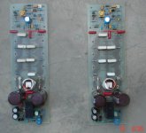
I spend the whole night and almost completed two Nmos350 channels.
I want you to have a look all the resistors I have used 1/4W the power resistors are 0.47ohm5w. Do you want me to double any resistor to achieve 0.5w or will it work fine?
regards
Wasim
I spend the whole night and almost completed two Nmos350 channels.
I want you to have a look all the resistors I have used 1/4W the power resistors are 0.47ohm5w. Do you want me to double any resistor to achieve 0.5w or will it work fine?
regards
Wasim
Attachments
lineup said:you want a preamp circuit.
I can do this.
But I know not enough information
============================
1. What will your preamp Output connect to?
Quasi NMOS350 or what power amplifier?
2. How much Watt you plan to output max from this Power ampllfier?
Into your Speakers.
3. What signal(s) will go into your preamp?
Sound input Sources like:
DAC, DAT-deck, mp3-player, iPOD, PC soundcard, turntable, cassette player,
CD-player or whatever .....
4. What op-amp should I use in my circuit?
cuMaybe one of your JRC4558 op-amps?
===========================
When I know this, I will make the best circuit I can.
To suit and fit and make everything right for your Audio Sound System.
Audio Sound System:
sound signal source -> (***preamplifier) -> power amplifier -> speakers
*** Some times we need no preamplifier.
This is better for hi-fi, if is possible to do so.
Some times we really need one preamplifier, to adjust and Make a bit higher voltage to the power amplifier input.
Regards
hi linup,
currently i need it for quasis nmos350,nmos200 and in future for
arctk400,600
the inputs are going to be PC soundcard and a cd player
regards
jethari said:
Hi, Ravs
Check out these links for pre-amps:
http://sound.westhost.com/project02.htm
http://sound.westhost.com/project88.htm
I'm using the one on project02 and its very good.
Hari
hi jethari
thanks for the links
ii have already seen those circuits
Hi ,Quasi
I have completed a full HT sub using your amp (modified brother
of Quasi - MJ15003 x 4) , now I want to build a modified Nmos 200 (4 output -IRF 240 version) .
What I would like to ask is can you put all 4 MJE 340/50's on the
main heatsink instead of the 2 drivers and VAS separate like on
your version.
I want to do this to simplify my layout and am concerned about
the effect on thermal tracking this change might produce.
By the way, your topology is very ideal for HT sub use,very strong
dynamic bass. A very rugged amp for room shaking abuse.
Thanks a $1M for this supurb design!!!
😎
What I would like to ask is
can you put all 4 MJE 340/50's on the main heatsink
instead of the 2 drivers and VAS separate like on your version.
I want to do this to simplify my layout
and am concerned about the effect on thermal tracking this change might produce.
Hello ostripper.
I would keep it like quasi has designed it.
Because you are very right:
This would produce changes in the thermal tracking.
Thermal Tracking is one of the more difficult things to do
when doing the final trimming for a welldesigned amplifier.
And this is what quasi has done .. for sure 😉
For this trimming you have to be clever & have good knowledge of transistor data and characteristics.
If you want to get your power amplifier right.
This is especially important for Class AB amplifiers as they have very different temperature
when low power and when higher power output.
Class A works more or less at Max temperature all the time.
With smaller differences & most often with less Thermal Tracking issues.
Thanks for the reply ,lineup .. but the reason I asked this was
because there are different layouts in the Quasi group of amps.
Namely, between the nmos 350/500 with all 4 340/350's on the U
shaped sink (vbe on main sink) and on the nmos 200 only VAS
340/350 on it's own sink (drivers and VBE on main sink). So , both amps seem to work good according to many DIY'ers even with this different layout .
Anyway, without any ill will , isn't this a "power amp under development" which means it should encouraged to modify it's
design in any manner or form ?
As stated in my last post , my "baby brother of Quasi" w/4
MJ 15003's is heavily modified with:
1. separate driver board
and point to point wiring to adapt to an old power supply
heatsink block.
2.LED constant current source w/.1uf bypass cap.(Aussie amps,
Ampslab,Elliot sound labs)
3.Outboard large fuses and Zobel network connected direct to PS
star ground.(cleaner driver board ground.)
4. Output inductor is the sub's lowpass Xover.(Quasi, is this acceptable?)
5.Absolutely overkill for a sub amp but I'm a perfectionist.
I thought putting all power devices on 1 heatsink would eliminate
the 'very warm VAS" I read about in some posts and maybe
greatly simplify construction.Also, the very small amount of heat
contributed by the VAS is a fraction of the total amp's dissapation.
I've already constructed bipolar version of this amp (listening to
floyd on it now 😎 😎 ) but have never made or even repaired a complete MOSFET amp.
ostripper said:Thanks for the reply ,lineup .. but the reason I asked this was
because there are different layouts in the Quasi group of amps.
-------
Anyway, without any ill will , isn't this a "power amp under development" which means it should encouraged to modify it's
design in any manner or form ?
-------
I thought putting all power devices on 1 heatsink would eliminate
the 'very warm VAS" I read about in some posts
and maybe
greatly simplify construction.
Also, the very small amount of heat contributed by the VAS
is a fraction of the total amp's dissapation.
You are right in much you say and
I am no expert on this special quasi model.
But my guess is that quasi have a good reason for add some extra heatsinks to VAS.
And this reason usually is of temperature issues.
If there wasn't, there would be plenty enough room on the Main Big heatsink!
Development it is!
But in this case is may be a less good development - an one way alley
that will force you go back.
But quasi will know better than me.
He knows his amplifiers like his own back-pocket 😎
I have never heard of anybody afraid of 'too warm vas'.
If is too warm, you just make the VAS heatsink a bit bigger.
-----------
Also, the very small amount of heat contributed by the VAS
is a fraction of the total amp's dissapation.
Think the other way, please 😉
The total worst case of Main heatsink heat, at high or full,
is a lot more than the VAS transistors may like to have.
Than if they are at their separate heatsink.
This is one good idea with having VAS in their own place:
they would not experience a lot of temperature difference at all.
As they usually will work in Class A = constant temperature (almost)
Wasim said:Hi Quasi,
I spend the whole night and almost completed two Nmos350 channels.
I want you to have a look all the resistors I have used 1/4W the power resistors are 0.47ohm5w. Do you want me to double any resistor to achieve 0.5w or will it work fine?
regards
Wasim
Hi Wasim,
You can use 1/4 watt resistors for all the low power resistors. The resistor biasing the two diodes in the ccs (R11) will get warm but still dissipating under 1/4 watt.
Cheers
Q
Re. Posts 2936 - 2929.
Hi Ostripper and Lineup.
The main reason for providing the VAS transistors with their own heatsink is to keep these close to the input stage. Placing these transistors on the main heatsink will require the use of longer tracks possibly compromising performance.
In the Nmos200 and BoQ* the VAS is still close to the input stage, but the board orientation for these amplifiers allows the output drivers to be placed on a heatsink bracket.
There are thermal considerations for the VAS. As the temeprature rises the current through this stage increases. As Lineup suggests this allowed for in the design and because this is a "class A" stage a balance is reached. If the VAS was placed on the main heatsink a final thermal balance may not be reached.
In the Nmos350 and Nmos500 it was convenient to place the output drivers on the same small heatsink as the VAS because it made the mounting of these devices simpler. The thermal changes for the driver stage transistors are small so mounting these on the same heatsink as the VAS still achieves a balance althought the heatsink will run warmer.
So I recommend that you keep the VAS close to the input stage on a seperate small heatsink. You can move the output drivers if you want.
This is indeed a power amp under development and it is in the public domain, so develop away!
Using an LED for the CCS voltage reference is cool** and should provide better ambient temperature tracking than the two diodes I have used. The voltage drop variance of LEDs is greater though so this should be checked when working out the CCS resistor.
The seperate driver board and other layout changes seem ok provided you keep the connections as short as possible.
The ouput inductor is there to help prevent RF picked up by the speaker leads from entering the feedback network. It has no significant effect at audio frquencies. The RC network at the output is to provide the amp with a load at high frequencies i.e, compensate for inductive loads. I wouldn't get hung up about any effect the coil might have on the "sonics", most of the talk about this is nonsense.
Anyway I'm glad you like these amps. Provided they are well built and powered by large high quality power supplies excellent results should be achieved.
Cheers & happy building
Quasi
* BoQ = Brother of Quasi
** no pun intended
Very good info .. will redesign my nmos 200 (4 x IRF260) board.
Good thing I did design my BOQ* board with separate VAS heatsinks.
You got me thinking in a different way about this amp thermally..
Since most of the gain of this amp is in the VAS ,
coupling it thermally with the output heatsink would increase thermal runaway when the outputs dissipation increases.?
Still , I want to keep as close to original specs as possible.
Since the amp I'm designing now is the one that will tickle my
golden ears (full range sony speakers), I just had to
ask 'the master' before I screwed up a good design.
If any want red a LED CSS , change r12/15 to 68 ohm and R7 to
270-330 ohm depending on led used .
Most red LED's have 1.65
1.7v forward drop(verses 1.4/1.5v for 2 diodes),
but don't count on it, test it first.(NO greens)!Also, add small cap .1/35v across LED for added stability.
This works very well in my completed BOQ* amp,no spice simulation, just cranked up HT sub.
While tinkering away like good ol' "Destroyer X" does
i've noticed
that the Quasi topology is very open to device changes such as
TO-126 devices for T8 etc. For HT sub use the only changes that make a difference are fat wires /traces and more caps .
.
Since I will soon have nearly identical BJT and NMOS Quasi"s
I will subject them to a head to head comparison and post at a
later date.
Thanks again Quasi, your last post shall be my design "bible".
Back to the graph paper ...(primative 😀 😀 )!!
Good thing I did design my BOQ* board with separate VAS heatsinks.
You got me thinking in a different way about this amp thermally..
Since most of the gain of this amp is in the VAS ,
coupling it thermally with the output heatsink would increase thermal runaway when the outputs dissipation
increases.?Still , I want to keep as close to original specs as possible.
Since the amp I'm designing now is the one that will tickle my
golden ears
(full range sony speakers), I just had toask 'the master' before I screwed up a good design.
If any want red a LED CSS , change r12/15 to 68 ohm and R7 to
270-330 ohm depending on led used .
Most red LED's have 1.65
1.7v forward drop(verses 1.4/1.5v for 2 diodes),
but don't count on it, test it first.(NO greens)!Also, add small cap .1/35v across LED for added stability.
This works very well in my completed BOQ* amp,no spice simulation, just cranked up HT sub.
While tinkering away like good ol' "Destroyer X" does
i've noticed
that the Quasi topology is very open to device changes such as
TO-126 devices for T8 etc. For HT sub use the only changes that make a difference are fat wires /traces and more caps
. Since I will soon have nearly identical BJT and NMOS Quasi"s
I will subject them to a head to head comparison and post at a
later date.
Thanks again Quasi, your last post shall be my design "bible".
Back to the graph paper ...(primative 😀 😀 )!!
Hi ostripper,
Would your circuit be the same as the TO-220 version and use IRPP260 instead of IRFP840. What else you have changed for your 4xIRPF260 version?
Would your circuit be the same as the TO-220 version and use IRPP260 instead of IRFP840. What else you have changed for your 4xIRPF260 version?
Hi, panda .
The only changes I have made to the original circuit
(NMOS 350v4)are
1. as above to the CCS and the layout of the board.It is a hybrid,looks like the NMOS 200-247 but has the
circuit of the NMOS 350.
2.Upped the wattage on R6,11,12,15,20,21,22 to 1W flameproof.
3.Used PC PS heatsink for 😱 cool VAS.(no ventilation in
sub box.)
For this power level I would recommend 44-0-44V tranny
and 15k for R7 off the chart on Quasi's web page.Also I
recommend you use Quasi's board(NMOS 350),
just omit 1 pair off of it.
With only 4 outputs no 2 ohm loads or bridging ,no
more than 60-0-60v supply (4 ohm) or maybe !!
I am making a truely custom board to fit in a recycled (trash)
commercial amp with 44-0-44 supply. I use .1 inch graph paper
,draw my layout,use a pin punch to center holes on FR-4
copper board , then sloooowly and carefully draw and paint
pattern on boards. The results are absolute beauty, a little
fatter traces than toner or photo method but still factory
quality.
As far as the performance of this amp is concerned ,I have only
built the bipolor version of this amp and I must say it blows
away any commercial offerings. It will "bottom out" my
Dayton 12" sub effortlessly without much heat or strain.
I cant wait to Hear the MOSFET version but can't afford
parts for it yet. Still ,at 40$ for parts you cant beat this amp.
(My brother of quasi only cost 25$-outputs... all other
parts were recycled from street junk. 😀
The only changes I have made to the original circuit
(NMOS 350v4)are
1. as above to the CCS and the layout of the board.It is a hybrid,looks like the NMOS 200-247 but has the
circuit of the NMOS 350.
2.Upped the wattage on R6,11,12,15,20,21,22 to 1W flameproof.
3.Used PC PS heatsink for 😱 cool VAS.(no ventilation in
sub box.)
For this power level I would recommend 44-0-44V tranny
and 15k for R7 off the chart on Quasi's web page.Also I
recommend you use Quasi's board(NMOS 350),
just omit 1 pair off of it.
With only 4 outputs no 2 ohm loads or bridging ,no
more than 60-0-60v supply (4 ohm) or maybe
!!I am making a truely custom board to fit in a recycled (trash)
commercial amp with 44-0-44 supply. I use .1 inch graph paper
,draw my layout,use a pin punch to center holes on FR-4
copper board , then sloooowly and carefully draw and paint
pattern on boards. The results are absolute beauty, a little
fatter traces than toner or photo method but still factory
quality.
As far as the performance of this amp is concerned ,I have only
built the bipolor version of this amp and I must say it blows
away any commercial offerings. It will "bottom out" my
Dayton 12" sub effortlessly without much heat or strain.
I cant wait to Hear the MOSFET version but can't afford
parts for it yet. Still ,at 40$ for parts you cant beat this amp.
(My brother of quasi only cost 25$-outputs... all other
parts were recycled from street junk. 😀
Andy L. Francis said:
Proper PSU wiring (see attachment!).
Thanks Andy L. Francis
Regards
NO , be very careful replacing T8 because it's gain (hfe) is what keeps your amp cool by reducing bias on output stage to
counteract "thermal runaway"🙂hot: hot transistors are better
conductors i.e. more gain).
I tried MJE 340 as T8 , amp didn't blow but became hot enough
to fry eggs on (hfe 30, not enough.Quasi chose BC546a (hfe 100)
or BC546 b/c (hfe 200+) better for poor ventilation..(my sub amp).
I am trying to find a suitable TO-126 device
so I can mount it near or right on an output device(saw this on a
ASKA amp,very good idea) and will try 2SC1567
which should be a very good VBE device (100v npn w/hfe 160)
slightly more robust tranny similar to BC546a/b.
Hi ostripper,
Thanks for the reply I was thinking about the MJE340 too but you have corrected my mistake.
Actually, I get some mounting problem ie that T8 is not completely attached with the main heat sink. Will that be a problem? Or should I make a hole into the main heat sink for T8?
Regards
Thanks for the reply I was thinking about the MJE340 too but you have corrected my mistake.
Actually, I get some mounting problem ie that T8 is not completely attached with the main heat sink. Will that be a problem? Or should I make a hole into the main heat sink for T8?
Regards
- Home
- Amplifiers
- Solid State
- Power amp under development