quasi said:The amp was never intended to run at 30 volts so I'm not sure how the biasing will work (at least I haven't worked it out).
If the amp appears to be working normally and the output offset is near zero volts then change the 100 ohm protection resistors to 10 ohms. Then see if you can bias the amp.
If this fails leave the 10 ohm resistors in and see if you can change the voltage across R20 and R22. As you turn the trimmer VR2 the voltage should change across these resistors indicating current flow through the 3rd stage. The output FETs will start to turn on at around 3.5 volts.
If you can not get to 3.5 volts, first check the current flows through the all the amp stages. If all looks good then you may need to change the values of R13 / R14. It could be that T8 is turned on too much and not allowing sufficient drive to the 3rd stage.
Finally for 30 volt rails R6 should be replaced with a link.
Cheers.
Q
I changed the resistors to 10 ohm. Same old problem stays.
Across R20 and 22, the voltage remains a maximum of 1.75V when there is a signal. When there is no signal the voltage is almost zero.
I need to check the current flow through all stages. Will do that and get back.
One thing I should mention is that there are potentiometers at the input. Will that make a difference? However, they are both turned to the minimum resistance position.
Thanks,
vivek
inverted transistors!
Hello Vivek, Quasi et al,
I just discovered a very wrong thing in my modules, and maybe Vivek has the same situation too.
My BC547s(replaced from BC546) and BC557 (from BC556) are all mounted in inverted manner? This means, that the CBE pin confiuration became EBC!...
As I stated previously, that I was having hard time getting the 30ma/FET pair....I would say, the FAirchi!d datasheet is so decieving.
But in all of these, they just show how good Quasi's ckt is. And that it still function so good even with the BC546/BC556 (and equivalent) are mounted invertedly.
Will update once I this working as designed.
BTW, I learned about my mistake when I re-examined my module and search for BC547 pinouts from google:
"http://images.google.com.ph/images?svnum=10&um=1&hl=en&q=bc547&btnG=Search+Images"
Joey
Attachments
Joey, was your amp working even with the transistors connected incorrectly? My amp produces an output as I found out yesterday. The sound is rather good but I am not able to bias the output transistors.
Hello Vivek,
Yes, my amp was sounding great. Very clear and so natural sounds. Actually, when I found this out, I could not believe
that the BC transistors were really mounted wrongly. I could only get up to 4volt voltage@100ohm then.
Last nite, I already corrected the mounting of the parts, and I can easily adjust the 100R voltage to 9V for my 3 FET pairs. I haven't tried yet on actual audio yet. Will try it tonite🙂.
In your case, I suggest you check the connection of T8. It may be mounted invertedly.
Rgds, Joey
Hi Volks,
you have confused me.
My Philips datasheets show the bc546/547/549/550 & bc556/557/559/560 as To92, sot54 and all have CBE assigned to pins 1, 2 & 3.
Fairchild also adopt the same pins configuration for the whole range including bc548/558
you have confused me.
My Philips datasheets show the bc546/547/549/550 & bc556/557/559/560 as To92, sot54 and all have CBE assigned to pins 1, 2 & 3.
Fairchild also adopt the same pins configuration for the whole range including bc548/558
The Philips data sheet is correct. The view is from the bottom.
Looking at the pins from the pin side ( bottom ) and keeping the flat face to the right , top to bottom you have C B E .
Data sheet from : http://www.ortodoxism.ro/datasheets/philips/BC546.pdf
Looking at the pins from the pin side ( bottom ) and keeping the flat face to the right , top to bottom you have C B E .
Data sheet from : http://www.ortodoxism.ro/datasheets/philips/BC546.pdf
AndrewT, Sorry for that. I want to correct that I was telling about the philips datasheets I downloaded and
not of fairchild's. Yes, Its just a matter of the bottom vs top view, and that's where I fell to new discovery of the quasi amp.🙂...
One problem i noticed with the inverted BC transistors is the excessive heat.
Joey
not of fairchild's. Yes, Its just a matter of the bottom vs top view, and that's where I fell to new discovery of the quasi amp.🙂...
One problem i noticed with the inverted BC transistors is the excessive heat.
Joey
volks77 said:
One problem i noticed with the inverted BC transistors is the excessive heat.
Joey
Joey
Excessive heat - on the 546 transistors or on the output pairs?
Hari
Just to come in:
We learned way back in the sixties that transistors had to be looked at as you look at a tube.
The pins represented by the fingers of your hand, pointing to your face.
Thumb, index and middle finger.
Here in Europe most transistors (small ones) are EBC (Thumb, Index, Middelfinger)
A tube is then: 1, 2, 3 etc starting from your thumb, index, middelfinger etc...
And I allways look it up in to a data sheet - book for a transistor I do not know; Allways!!!
Here a GOOD link:
http://www.datasheetcatalog.com
Cheers,
Zilog
Thanks, Tarzan, for the bits of learning you shared.
Hello Jethari,
The excessive heat is both on the MJE340/350 and FETs heatsinks. I could endure heat on the MJE's but could not hold on the FET heatsink more than 3secs.
The amazing part is, the sound was so good. I might explore on this once my nmos350 plays while inside good enclosure.
Joey
Hello Jethari,
The excessive heat is both on the MJE340/350 and FETs heatsinks. I could endure heat on the MJE's but could not hold on the FET heatsink more than 3secs.
The amazing part is, the sound was so good. I might explore on this once my nmos350 plays while inside good enclosure.
Joey
The MJE340/350s and their heatsink will get very warm (hot?) but this is ok because these transistors are doing very light average duty and have plenty of room to spare in terms of thermal derating.
The main heatsinks on the other hand should never run any hotter than comfortable warm (you can hold them with comfort forever). This is because the output devices are not doing light duty and when thermal derating is taken into consideration there isn't that much room to spare.
So be generous with the main heatsinks. Take a look at my and others builds to get the idea.
Cheers
Q (amp modules that work irrespective of transistor orientation??)
Hi All.. just back from my holiday.
3rd Attempt after replacing T7 (MJE340). VR1 and VR2 both turn to minimum position (counter clockwise).
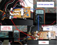
Power Up with +-56Vdc (shows on voltmeter) and getting 5.16 Vdc on Neg Rail side and -14.99 on Pos Rail side both measurement taken across 100r safety resistor. Then below 1min, minor smoke coming up from T6 area only for few second. T7 seems to be ok!!! (is what I thought so).
All 4MJE's and FET already checked for contact with heatsink before power up.
100r at the Pos Rail side seems a little bit warmer compared with the one at the Neg Rail side. very frustrating...
Anything to suggest guys.... BDW how to check if either one of the 4 MJEs fail? Or Is still save to continue power up and do the calibration?
Help Me...
3rd Attempt after replacing T7 (MJE340). VR1 and VR2 both turn to minimum position (counter clockwise).
Power Up with +-56Vdc (shows on voltmeter) and getting 5.16 Vdc on Neg Rail side and -14.99 on Pos Rail side both measurement taken across 100r safety resistor. Then below 1min, minor smoke coming up from T6 area only for few second. T7 seems to be ok!!! (is what I thought so).
All 4MJE's and FET already checked for contact with heatsink before power up.
100r at the Pos Rail side seems a little bit warmer compared with the one at the Neg Rail side. very frustrating...
Anything to suggest guys.... BDW how to check if either one of the 4 MJEs fail? Or Is still save to continue power up and do the calibration?
Help Me...
Attachments
Volks, I have connected T8 correctly. I think I will have to remove the 33 ohm resistor and also check the current flow like Quasi suggested.
Vivek,
Both your rail voltage is it balance (same reading between both rail to ground - with only +/- difference)?
Found 1 big mistake where T8 was mounted on the top side of the pcb. Will correct the error soon if the T8 still ok. Is this causing the unbalance voltage between rail?
Both your rail voltage is it balance (same reading between both rail to ground - with only +/- difference)?
Found 1 big mistake where T8 was mounted on the top side of the pcb. Will correct the error soon if the T8 still ok. Is this causing the unbalance voltage between rail?
My experience with minr smoke, is normally overheating resistors... the paint lets off some smoke.. but only a few times.. then it normally gets worse...
Hi satcure645,
I also experience the same. After correcting my nmos350 modules,
It was handly to adjust the 100R voltage to +9V (only -7.6 on neg rail). But after returning the fuse and powered one module, the 220R@T10 and neg rail fuse burned. I guess there is excessive current running thru the 200R whic causes is to burn.
For now, I don't trust the 100R biasing technique. Sorry for this deviation. I now use "sense of touch". I only set 2V on the 100R
then returned the fuse. I notice that the FETs are getting just slightly warm. Then I adjusted gradual on CW direction, until I felt the heatsink with enough warmness.
I think best method is to measure the actual current on the 0.33 ohms, either by measuring the voltage drop or the current.
Joey
FWIW, I always use the kill or cure method. Connect the completed PCB to the designed power supply using 1A fast blow fuses for both rails. Power supply transformer using 1A slow-blow. Bias adj at center of travel. Multimeter at mA range across one of the emitter resistors. Turn ON and pray that there will not be shrapnels everywhere. Have worked for over 10 years of amp building. Well, I did blew a few capacitors.......
volks77 said:Hi satcure645,
I also experience the same. After correcting my nmos350 modules,
It was handly to adjust the 100R voltage to +9V (only -7.6 on neg rail). But after returning the fuse and powered one module, the 220R@T10 and neg rail fuse burned. I guess there is excessive current running thru the 200R whic causes is to burn.
For now, I don't trust the 100R biasing technique. Sorry for this deviation. I now use "sense of touch". I only set 2V on the 100R
then returned the fuse. I notice that the FETs are getting just slightly warm. Then I adjusted gradual on CW direction, until I felt the heatsink with enough warmness.
I think best method is to measure the actual current on the 0.33 ohms, either by measuring the voltage drop or the current.
Joey
Volks
"Experience the same" means T8 wrongly place at the top of the pcb? I've already corrected my T8 position to the bottom of the pcb and locate the T8 at the main heatsink.. (current heatsink definately can't stand the heat-to small-fin type with fan) will change to bigger size once the NMOS module running fine.
Mine using 0.47 Ohms..BDW after power-up with T8 corrected still getting unbalance voltage between both rails to Gnd i.e. - 16.3 Vdc at (Neg Rail) and + 5.05 Vdc (Pos Rail). No idea where's to check next... should I adjust VR2 - any suggestion?
bawang said:Multimeter at mA range across one of the emitter resistors.
If the multimeter is across the emitter resistor, then it should be set to the mv/V range; not the current range.
- Home
- Amplifiers
- Solid State
- Power amp under development