Quasi
After a lot of scraping and polishing, I've got my module going again this time with two pairs. I've even used mica insulators this time but am not very happy with them. I'll go back to the silicone rubber insulators. The heat transfer onto the heatsink is much better now, the mosfets have not blown so far. As I mentioned earlier, the sound quality is simply awesome 😀
There is something bothering me - in the schematic of both the 350 and the 200 the fuses are inserted only for the supply for the output pairs. But the nmos200 layout has the fuse inserted for the driver pair as well (T9 and T10) and this is how I have also made the layout. Will this have any bearing on the current measured at the fuse? If my assumption is right, according to your schematics and the nmos350 layout when we measure the current at the fuse its only the current that is flowing through the output pairs.
Hari
jethari said:Satcure
If you're getting 17.1V and 13.2V across the resistors, there is something wrong.
Firstly the voltage across both the resistors should be the same unless the resistor values are different. Measure the resistor values accurately.
Secondly, if the resistor values are correct, you still have a problem. The current is too high - 132 or 171 ma. This is way too high even for a three pair config. I hope you've not got the speaker connected to the output while measuring. While setting up the bias, the input should be shorted and the output must be open
Lastly, try using a higher voltage supply - around +/- 40V DC to get a more realistic picture.
Hari
Thanks for the quick reply.. will post the result soon after checking somewhere in the morning. it's now late at night in malaysia @2.14am.
Attachments
Hi,
if your supply is 22Vdc and the drop across the fuse holder is 13Vdc, then that part of the circuit is powered by just 9Vdc instead of 50Vdc.
You must turn down the bias to zero and recheck the quiescent currents.
Then reduce the resistors to 10r and start turning up the bias. If the output offset is still OK then replace the test resistors with 1r0 and do your final setting up.
AndrewT said:Hi,
if your supply is 22Vdc and the drop across the fuse holder is 13Vdc, then that part of the circuit is powered by just 9Vdc instead of 50Vdc.
You must turn down the bias to zero and recheck the quiescent currents.
Then reduce the resistors to 10r and start turning up the bias. If the output offset is still OK then replace the test resistors with 1r0 and do your final setting up.
Thanks...a few more question before i blow up my amp...hehehe
What about the differential between both rail voltage to Gnd..i.e 13.24Vdc & -17.10Vdc anything that i can do? Already measured both resistor and it shows correct value at 100Ohm.
Anyway will used 10r as suggested by but just in-case there are still different voltage reading between both rail to Gnd voltage reading...what should I check next if both 10r is ok?
For your info..Last measurement was done with "open input terminal" not closed or shorted as suggested. Will try soon (morning).
Hello Satcure645
The amp is not designed to work at such low voltages even though it probably will as you have discovered.
You must though replace R6 with a link so that the constant current source transistor T4 has sufficient voltage across it. When you build your larger power supply, remember to put it back (use the table on my web site as a guide).
With no input or output connected set the amp up as AndrewT has suggested, although I would not bother with the 1 ohm resistors if the 10 ohm voltages check out ok. Check to see that the ouput voltage at idle (output offset voltage) is under 10mV.
Refer to the setup section contained in the construction guide also found on my web site.
Just a note; When you buy the 55v 0 55v 500VA transformer you will end up with DC rails of between 75 and 80 volts and this will be too much for your capacitors. You will also need to upgrade the heatsink.
Kind Regards
Quasi
Hello Hari,
Your welcome. I thought I pass the information on based on the many experiences I have had related to wood finishing where we need to remove a previous finish before we start with the new finish the customer requested.
Emery paper as you discovered works just as well, if not better for your circumstance and the fact you are working with metal. The comments I made about grade would remain unchanged. Great you have a smooth finish now. It should translate to more surface area contact ergo reduced thermal resistance.
The fact the MOSFETs are stone cold under no signal condition is very encouraging. That said you can still have oscillation issues. One would be the Glow-No Glow-Glow-No Glow light bulb result when the light bulb is in series with the AC Live/Hot side. The other possibilities may be related to the PCB layout wherein some unexpected capacitance exists between traces that may be altering the frequency compensation of the designed circuit, the Zobel network may need refinement with respect to speaker load/crossover/cable, there may be some unusual RF entering the circuit at the input, output/speaker cable or matches a tuned frequency of the PCB, cold solder joint, defective part, et al. As stated previously it can be any of these in combination as well. Some other builder found the L1 coil he made for the Zobel network was not the inductance he thought it was and had to make a new coil.
It may be worth using the light bulb test not just with no signal, but also with a signal just to see if at low signal levels the behaviour of the bulb suggests there may be oscillations. At medium to higher signal levels the blub will glow. That said if the bulb cycles between Glow and No Glow using steady state signal then there is an oscillation issue which has been suggested as a grounding issue. Ground loops can be such a challenge to find and solve.
I know there has been some discussion of what to use as a divider for a soundcard CRO/Meter based measuring system. I am not sure on how specific the values of the divider should be with respect to the specific sound card being used. It is very likely you will need to scope the output under the signal/load conditions that MOSFETs appear to get too warm, assuming the issue was not related to the thermal resistance of the amount of thermal compound/silicon pad combination, "L" bracket, and heatsink interfaces. Personally after you have all the MOSFETs remounted with the cleaned and sanded down heatsink parts I would see if you still have the MOSFET localized heating you observed with the heatsinks still cold. That initial issue you observed seems suggestive there was a thermal interface issue with the MOSFETs to the heatsink. Of course you want to go slow on this retest to be certain there is no other issue or a worse issue at hand. It would make sense o have the light bulb in series with the Live/Hot AC to the transformer of the PSU just as a bit of extra protection during the testing.
I think using a dummy load for part of the testing would be a good intermediate step. The first dummy load I would use would be just a resistive load. You are best to try a 8 ohm resistive load. I would ensure the load can handle about 20 watts. You will need to use non-inductive resistors which likely means at best 2W resistors. That would mean 10 x 2W resistors in parallel. If my Ohms Law math is correct you would need 10 x 80 Ohm resistors in parallel to equal an 8 ohm 20W load. If all goes well with the 8 ohm resistive test and no thermal issue arise of concern, I would move onto replacing the dummy resistive load with your speaker load you had been using and compare your results/observations. If all appears well with the iPod and speakers connected I would remove the light bulb in series with the AC line and again test in a graduated manner while of course keeping an eye on the MOSFETs and heatsink temperatures.
Hari, I know it sounds like alot of steps/iterations, but I think you will agree you rather avoid blowing anymore devices. Oh I assume you have checked or replaced other devices, including passives after your instances of the MOSFETs blowing in the initial instances? That point is indirectly related to defective part(s) being a possible cause to the problems.
Regards,
John L. Males
Willowdale, Ontario
Canada
06 January 2007 (10:30 -) 11:20
Official Quasi Thread Reseacher
jethari said:John
Thanks for the detailed instructions. In fact I had to use 80 grade emery cloth for removing the coating (whatever it was). I do indeed have sanding blocks of various sizes which I was using during my speaker building project. I've sanded the heatsink to quite a smooth finish.
Your welcome. I thought I pass the information on based on the many experiences I have had related to wood finishing where we need to remove a previous finish before we start with the new finish the customer requested.
Emery paper as you discovered works just as well, if not better for your circumstance and the fact you are working with metal. The comments I made about grade would remain unchanged. Great you have a smooth finish now. It should translate to more surface area contact ergo reduced thermal resistance.
As regards oscillations, the mosfets are stone cold under no signal conditions. Does this mean anything vis a vis oscillations? Also, there are no unwanted sounds from the speaker when there is no signal. I do not have a CRO but have a CRO programme installed on my laptop which uses the sound card for input and output. To use this what kind of potential divider should I have so as not to blow up the sound card?Should I also use a dummy load and if so what value?
Thanks
Hari
The fact the MOSFETs are stone cold under no signal condition is very encouraging. That said you can still have oscillation issues. One would be the Glow-No Glow-Glow-No Glow light bulb result when the light bulb is in series with the AC Live/Hot side. The other possibilities may be related to the PCB layout wherein some unexpected capacitance exists between traces that may be altering the frequency compensation of the designed circuit, the Zobel network may need refinement with respect to speaker load/crossover/cable, there may be some unusual RF entering the circuit at the input, output/speaker cable or matches a tuned frequency of the PCB, cold solder joint, defective part, et al. As stated previously it can be any of these in combination as well. Some other builder found the L1 coil he made for the Zobel network was not the inductance he thought it was and had to make a new coil.
It may be worth using the light bulb test not just with no signal, but also with a signal just to see if at low signal levels the behaviour of the bulb suggests there may be oscillations. At medium to higher signal levels the blub will glow. That said if the bulb cycles between Glow and No Glow using steady state signal then there is an oscillation issue which has been suggested as a grounding issue. Ground loops can be such a challenge to find and solve.
I know there has been some discussion of what to use as a divider for a soundcard CRO/Meter based measuring system. I am not sure on how specific the values of the divider should be with respect to the specific sound card being used. It is very likely you will need to scope the output under the signal/load conditions that MOSFETs appear to get too warm, assuming the issue was not related to the thermal resistance of the amount of thermal compound/silicon pad combination, "L" bracket, and heatsink interfaces. Personally after you have all the MOSFETs remounted with the cleaned and sanded down heatsink parts I would see if you still have the MOSFET localized heating you observed with the heatsinks still cold. That initial issue you observed seems suggestive there was a thermal interface issue with the MOSFETs to the heatsink. Of course you want to go slow on this retest to be certain there is no other issue or a worse issue at hand. It would make sense o have the light bulb in series with the Live/Hot AC to the transformer of the PSU just as a bit of extra protection during the testing.
I think using a dummy load for part of the testing would be a good intermediate step. The first dummy load I would use would be just a resistive load. You are best to try a 8 ohm resistive load. I would ensure the load can handle about 20 watts. You will need to use non-inductive resistors which likely means at best 2W resistors. That would mean 10 x 2W resistors in parallel. If my Ohms Law math is correct you would need 10 x 80 Ohm resistors in parallel to equal an 8 ohm 20W load. If all goes well with the 8 ohm resistive test and no thermal issue arise of concern, I would move onto replacing the dummy resistive load with your speaker load you had been using and compare your results/observations. If all appears well with the iPod and speakers connected I would remove the light bulb in series with the AC line and again test in a graduated manner while of course keeping an eye on the MOSFETs and heatsink temperatures.
Hari, I know it sounds like alot of steps/iterations, but I think you will agree you rather avoid blowing anymore devices. Oh I assume you have checked or replaced other devices, including passives after your instances of the MOSFETs blowing in the initial instances? That point is indirectly related to defective part(s) being a possible cause to the problems.
Regards,
John L. Males
Willowdale, Ontario
Canada
06 January 2007 (10:30 -) 11:20
Official Quasi Thread Reseacher
John
I think in all probabilities it was a problem of ineffective heat transfer. With the mating surfaces properly polished and the "right" amount of heat sink compound applied, the heat sink has started absorbing the heat. I've been testing the module with the ipod and speaker the whole day today. Though the mosfets are getting hot it is quickly being dissipated into the heat sink. I've driven it quite hard without blowing the mosfets 😀 Apparently the temperature on the plastic part of the case is not very indicative of the junction temperatures.
I'll still go for the light bulb experiment to look for oscillations. In my past experiments with amps, whenever there were ground loop problems it used to result in an audible hum or a buzz from the speaker. This hum or buzz would remain irrespective of the presence or absence of input signal. All the same I'll check it out.
Any comments on the size of the heatsink I'm using? Is it adequate for a two pair version running +/- 65V?
Hari
After reading all your comments, it's better for me to perform the SETUP with the actual transformer value as suggested by Quasi. Decided to go for 500VA 44Vac instead of 55Vac due to Caps bank currently installed with 4 x 10000uF 63Vdc.
As such I will change the Resistor R6=12 Ohm and R17=27 Ohm as per Quasi "Power Selection Guidelines".
Any comment? Will post the update once the "Transfo" ready.
Many Thanks Guys
As such I will change the Resistor R6=12 Ohm and R17=27 Ohm as per Quasi "Power Selection Guidelines".
Any comment? Will post the update once the "Transfo" ready.
Many Thanks Guys
s such I will change the Resistor R6=12 Ohm and R17=27 Ohm as per Quasi "Power Selection Guidelines".
Warning! These resistors are 12kOhm and 27kOhm!
Hi,
using the normal tolerances on mains and transformers, the highest voltage for 63Vdc smoothing caps is about 40 to 41Vac, not 44Vac.
using the normal tolerances on mains and transformers, the highest voltage for 63Vdc smoothing caps is about 40 to 41Vac, not 44Vac.
satcure645 said:After reading all your comments, it's better for me to perform the SETUP with the actual transformer value as suggested by Quasi. Decided to go for 500VA 44Vac instead of 55Vac due to Caps bank currently installed with 4 x 10000uF 63Vdc.
As such I will change the Resistor R6=12 Ohm and R17=27 Ohm as per Quasi "Power Selection Guidelines".
Any comment? Will post the update once the "Transfo" ready.
Many Thanks Guys
satcure654,
I would not use a 44-0-44 secondary voltage transformer with 63V filter capacitors. 44 * sqrt(2) = 62.2V DC. The PSU filter capacitors will either overheat from the ripple currents and/or the filter capacitors will have a very short life. you need to have at least a 10% margin, 20% is better. At most you can use a transformer primary of (63V * 0.9) / sqrt(2) =
40.0V. For a 20% margin you would use (same formula using 0.8 for the 20%) a 35.5V secondary, so 35-36 would be the 20% margin.
Ideal power handling for 8 ohms resistive would be V**2/8. So for 40V-0-40V transformer that would be 200W RMS, 400W peak. For a 35V-0-35V transformer you would have about 150W RMS and 300W peak for 8 ohms resistive.
For a normal speaker with a passive crossover you would divide the above values by 2.
You would double the above values again for the respective 4 ohm loads for ideal PSU, but you would not likely reach more than 80% of those values due to PSU sagging at lower output impedances.
Current handling would for a resistive 8 ohm load would be V/R. For 40-0-40V transformer that would be 5A RMS and 7A peak. For 35V-0-35V transformer that would be 4.4A RMS and 6.2A peak.
The VA rating would then be Vx2*A. For 40V-0-40V this would be 200VA per amplifier module into 8 ohm resistive. For 35V-0-35V this would be 150VA per amplifier module into 8 ohm resistive.
So if you use one transformer to drive two amplifier modules you would need a 400VA 40V-0-40V transformer or a 300VA 35V-0-35V transformer.
Because these are RMS VA ratings and one will never have a pure sine wave RMS driving the amplifier with music. For this reason these above VA ratings would be generally be ok for most domestic music listening with 8 ohm speakers and their related passive crossover networks.
I would double the above VA ratings (per module) for a 4 ohm passive crossover speaker.
I hope this helps you make your decision about what transformer size you will use or if you will find higher rated PSU filter capacitors.
Regards,
John L. Males
Willowdale, Ontario
Canada
06 January 2007 (13:00 -) 13:45
Official Quasi Thread Researcher
jethari said:John
I think in all probabilities it was a problem of ineffective heat transfer. With the mating surfaces properly polished and the "right" amount of heat sink compound applied, the heat sink has started absorbing the heat. I've been testing the module with the ipod and speaker the whole day today. Though the mosfets are getting hot it is quickly being dissipated into the heat sink. I've driven it quite hard without blowing the mosfets 😀 Apparently the temperature on the plastic part of the case is not very indicative of the junction temperatures.
I'll still go for the light bulb experiment to look for oscillations. In my past experiments with amps, whenever there were ground loop problems it used to result in an audible hum or a buzz from the speaker. This hum or buzz would remain irrespective of the presence or absence of input signal. All the same I'll check it out.
Any comments on the size of the heatsink I'm using? Is it adequate for a two pair version running +/- 65V?
Hari
Hi Hari,
Excellent your heatsinks are now "heatsinking". I think your prior noted observations that the MOSFETs were getting warm/hot, but the heatsink was cold was the telling element of the possible cause. I do not have alot of experience with such matters so I was unsure if oscillations might cause localized MOSFETs heating or that even when the thermal interfaces were corrected if there was still some other underlying problems.
The light bulb test at best might uncover some grounding based issues. While it is true you can often hear oscillations many builders for other projects, besides the couple that have had such problems with their build of this project, have had oscillation issues that do not manifest as a hum or buzz noise. Another manifestation can be in terms of muddy sound quality, distortion and/or "unexplained" clipping.
The "L" bracket you are using for the PCB/MOSFETs to main heatsink is great as it has lots of surface area to distribute the heat onto the main heatsink. The main heatsink is hard to see from the pic you posted in terms of fin pattern/area. I would say the main heatsink is on the small side if the amp is pushed moderately for any length of time. If you need to stay with that dimensioning of heatsink for a long time I would look into finding a thermal cutoff you can mount on the main heatsink that would cut off the PSU if the temperature goes above 60C. Then you can use the smaller heatsink and have the protection of the thermal cutoff just in case something goes wrong or the input signal is accidentally set too high.
As a side note, once you are happy your PCB is stable and has no errors (one PCB error in the quasi version slipped by for about 2 years before it was discovered by a builder) I like to et a copy of the PCB images and the Protel schematic/PCBs so I can modify the PCBs. I assume you will add the capacitor across T8 that was missing from the schematic you based your PCB on. There is also a few other components that are optional I like to add. I like a pair of onboard filter capacitors rather than single one, splitting the supply rails, and some of the capacitors I have sourced are different sizes, all be it larger in most cases, but at the "right" surplus price and excellent quality. I would like to see if using a copy of Protel that I may be able to find will make that process easier and less time consuming then the current method I use of modifying the PCB image with a graphics program. I am in no hurry at moment for the files, but I made single pair and two pair versions of the "classic" quasi PCB layout as in most cases I for my needs I do not forsee needing more than one or two pairs of output devices. The difference with the NMOS200 layout quasi came out with which you modeled your PCB to for a NMSO350 version is the ability to stack the PCBs to a heatsink. I like the choice of both options which may give me more case and heatsink options for any related surplus hardware I may be able to still find.
Regards,
John L. Males
Willowdale, Ontario
Canada
06 January 2007 (13:47 -) 14:24
Official Quasi Thread Researcher
keypunch said:
The "L" bracket you are using for the PCB/MOSFETs to main heatsink is great as it has lots of surface area to distribute the heat onto the main heatsink. The main heatsink is hard to see from the pic you posted in terms of fin pattern/area.
John
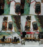
the main heat sink is 8"X2.75"X0.75". Here is a clearer pic of the same.
Hari
Attachments
Thanks again....what a details explanation -
I will reconsider if either to upgrade the Caps bank voltage or getting lower value transfo.. still didn't know what I'm doing...just to have my own DIY amplifier ready as a satisfaction to myself but for sure with a lot of help from you guys out there.... thanks again for highlighting the Resistor R6 & R17 value as i already bought the wrong one..will keep posting soon.
😎 Cheers
Hi Hari,
I'm also very glad to hear it worked out as expected.
This goes to show what a difference heat transfer between junctions - and the right application of thermal grease - can make. Great! 😉
Quite honestly, I don't think so! 🙂
Cheers,
Sebastian.
jethari said:I think in all probabilities it was a problem of ineffective heat transfer. With the mating surfaces properly polished and the "right" amount of heat sink compound applied, the heat sink has started absorbing the heat.
I'm also very glad to hear it worked out as expected.
This goes to show what a difference heat transfer between junctions - and the right application of thermal grease - can make. Great! 😉
Any comments on the size of the heatsink I'm using? Is it adequate for a two pair version running +/- 65V? ...the main heat sink is 8"X2.75"X0.75"
Quite honestly, I don't think so! 🙂
Cheers,
Sebastian.
Quite honestly, I don't think so! 🙂
Cheers,
Sebastian. [/B]
I thought so too! I'll come up with some idea for that soon. Meanwhile the testing is still on.
Hari
zerohead_ak47 said:hi quasi
did you try this circuit ?
what do you think about its quality ?
This circuit is one of my other designs found here; http://www.diyaudio.com/forums/showthread.php?postid=595571#post595571
It sounds just fine although it has been further developed since then. I note the file name has changed so I would be interested to find out where you found it.
Cheers
Quasi
jethari said:
I thought so too! I'll come up with some idea for that soon. Meanwhile the testing is still on.
Hari
sek
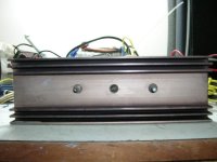
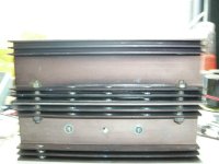
Take a look at this arrangement. I stacked two of them together. I tested it for quite some time at quite high levels, feels much better now.
Hari
Attachments

- Home
- Amplifiers
- Solid State
- Power amp under development