quasi said:
Gday Hari,
Can you please post a photo showing the mounting of the output FETs. It could be that you are not removing the heat well enough. On the original Nmos350 the FETs are mounted directly onto a large heatsink.
If you have access to a CRO and a signal generator have a look at the output for possible oscillations.
Cheers fellas
Q
Quasi
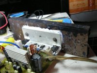
I'm having the same doubt regarding effective heat sinking. When I mentioned that the mosfets are running hot, I was checking the heat directly on the mosfets. The heat sink was not all that hot. Here is a pic of the arrangement.
Hari
Attachments
Hi Hari,
Can you tell me please what rails you are running?
If the FETs are getting to hot then you have either inadequate heat removal or some oscillations.
As an observation your heatsink bracket seems too thin for continued high power use.
Also as aside, you have used way too much heat transfer grease. There is only supposed to be a smear between the device and the heatsink. I might be a good idea to clean the bracket up and re-tighten the mounting bolts.
Cheers
Q
Quasi, pejinm
Thanks for the suggestions. I'll straight away get down to it. Should I apply the thermal grease on both sides of the insulating piece between the mosfet and the bracket or only one side. In fact the insulators that I am using claim to be made from thermally conductive silicone rubber.
http://www.rapidonline.com/producti...=Silicone+rubber+mounting+kits&moduleno=32693
hari
nmos200 pcb dimension
First, I like to thank Quasi for this wonderful design that was developed and still under development.
In regards to this, I am interested in building the nmos200. May I know the dimension of the pcb. I tried to locate at Quasi's site but I saw none. Thanks.
First, I like to thank Quasi for this wonderful design that was developed and still under development.
In regards to this, I am interested in building the nmos200. May I know the dimension of the pcb. I tried to locate at Quasi's site but I saw none. Thanks.
needs nmos200 pcb dimension
Want to add also that I just built the nmos500, and very satisfied with the results...no hiss, no hum and very clear sounds. My power supply is 2X 50vac with 36MF caps. Hope to place it in an enclosure soon....
But at this point I decided to build the NMOS200. Tried to re-browse the whole thread but didn't notice the PCB dimension.
Hello Hari or anyone, may I know the exact pcb dimension of nmos200. I am thinking of bridging two of this quasi variant.
Thanks.
Re: nmos200 pcb dimension
Dimensions of the Nmos200 PCB's are;
74.9mm x 89.9mm for the TO220 version
74.9mm x 94.6mm for the TO247 version
Glad you like your amp.
Cheers
Q
volks77 said:First, I like to thank Quasi for this wonderful design that was developed and still under development.
In regards to this, I am interested in building the nmos200. May I know the dimension of the pcb. I tried to locate at Quasi's site but I saw none. Thanks.
Dimensions of the Nmos200 PCB's are;
74.9mm x 89.9mm for the TO220 version
74.9mm x 94.6mm for the TO247 version
Glad you like your amp.
Cheers
Q
IRFZ34
Thanks a lot, Quasi. Yes, i'm very amazed with the clarity of the sounds.
I am having struggle though with the biasing the mosfets with 15volts. I only settled at 4volts. And due to this, I downgraded it to 3pairs. I also noticed that the irfp450s quickly get hot. BTW, since I'm having hard time getting BC546/BC556 parts, I settled to BC546/BC547. I hope there is not a problem using them.
Now for the NMOS200 project, I'm planning to mount 2 pairs of IRFZ34 mosfets. Do you think these mosfets are okay to use?
thanks again.
JoeyG
Hello Hari,
The thermally conductive silicone is good as is, at least that's how the manufacturer designed it.
This means they require no grease at all. If in doubt, either clean and remount them or replace them with mica or - better yet - ceramic washers. Those would require grease, though.
I think Quasi and Penjim also referred to the transition between mounting bracket and the cast heat sink rail. The surface of the large heat sink really looks dirty and uneven. By dirt I mean anything except bare alluminium, i.e. laquer.
Thermal grease should always be applied the minimalist way: as much as needed but as few as possible. You recognize a good thermally conductive joint from the fact that no excess grease spills out but no further amount of grease would fit in. If this is not possible, your surface is too uneven. Please note that the grease stuff is not intended to transfer heat as such, but only to fill the tiny gaps inbetween the mating surfaces.
Sanding could be your solution. There's no reason the area where the bracket meets the rail can't be sanded smooth. From experience I recommend starting with no rougher than No.240 and finishing with at least No.1000 paper. Then apply grease and pull it off using a blade or some other flat and even tool.
Hope this helps,
Sebastian.
jethari said:Should I apply the thermal grease on both sides of the insulating piece between the mosfet and the bracket or only one side. In fact the insulators that I am using claim to be made from thermally conductive silicone rubber.[/url]
The thermally conductive silicone is good as is, at least that's how the manufacturer designed it.
This means they require no grease at all. If in doubt, either clean and remount them or replace them with mica or - better yet - ceramic washers. Those would require grease, though.
I think Quasi and Penjim also referred to the transition between mounting bracket and the cast heat sink rail. The surface of the large heat sink really looks dirty and uneven. By dirt I mean anything except bare alluminium, i.e. laquer.
Thermal grease should always be applied the minimalist way: as much as needed but as few as possible. You recognize a good thermally conductive joint from the fact that no excess grease spills out but no further amount of grease would fit in. If this is not possible, your surface is too uneven. Please note that the grease stuff is not intended to transfer heat as such, but only to fill the tiny gaps inbetween the mating surfaces.
Sanding could be your solution. There's no reason the area where the bracket meets the rail can't be sanded smooth. From experience I recommend starting with no rougher than No.240 and finishing with at least No.1000 paper. Then apply grease and pull it off using a blade or some other flat and even tool.
Hope this helps,
Sebastian.
Thermally conductive rubber doesn't need additional grease. It is like grease with a compound and will deform under pressure to fill the small holes between heatsink and device.
Jan Didden
Jan Didden
sek said:This means they require no grease at all.
janneman said:Thermally conductive rubber doesn't need additional grease.
Citation from the manufacturer's site
[...] there is no need to use messy and time-consuming heatsink compounds.
Great to see we all seem to agree on this. 😀
Re: IRFZ34
Hi Joey,
I think you meant BC557 and you can use these no problems.
The IRFZ34 are probably not suitable as they are only rated at Vdss = 60v. The FET used must be rated to at least the full rail to rail difference, i.e. if the rails are +/- 50v then a FET rated to Vdss = 100v must be used. If you used IRFZ34's then you must limit your rails to 30 volts (and what would be the point in that?).
Cheers
Q
volks77 said:Thanks a lot, Quasi. Yes, i'm very amazed with the clarity of the sounds.
I am having struggle though with the biasing the mosfets with 15volts. I only settled at 4volts. And due to this, I downgraded it to 3pairs. I also noticed that the irfp450s quickly get hot. BTW, since I'm having hard time getting BC546/BC556 parts, I settled to BC546/BC547. I hope there is not a problem using them.
Now for the NMOS200 project, I'm planning to mount 2 pairs of IRFZ34 mosfets. Do you think these mosfets are okay to use?
thanks again.
JoeyG
Hi Joey,
I think you meant BC557 and you can use these no problems.
The IRFZ34 are probably not suitable as they are only rated at Vdss = 60v. The FET used must be rated to at least the full rail to rail difference, i.e. if the rails are +/- 50v then a FET rated to Vdss = 100v must be used. If you used IRFZ34's then you must limit your rails to 30 volts (and what would be the point in that?).
Cheers
Q
Sek, janneman
Thanks a ton for the gen on thermal grease and thermal coupling. I will clean all the grease from the silicone rubber insulators and yes, even I felt that the main heat sink surface is not quite right. I think its got some kind of coating on it. I'm going to scrape it down to the bare aluminium and polish it (at least the contact area with the bracket). I'll keep you guys posted as soon as it is done.
Hari
It does not need to be polished. But, it must be FLAT.jethari said:scrape it down to the bare aluminium and polish it (at least the contact area with the bracket).
jethari said:Sek, janneman
Thanks a ton for the gen on thermal grease and thermal coupling. I will clean all the grease from the silicone rubber insulators and yes, even I felt that the main heat sink surface is not quite right. I think its got some kind of coating on it. I'm going to scrape it down to the bare aluminium and polish it (at least the contact area with the bracket). I'll keep you guys posted as soon as it is done.
Hari
Yes; in the end the temperature of the device metal flange should not be much higher than the heatsink bracket, that will indicate good heat transfer. I think that was not good in your case.
Also note that the plastic top of the device is normally quite a bit hotter than the metal part, so don't worry about that. It's the metal part that is in intimate contact with the die and ultimately responsible to get the heat out.
Jan Didden
sek said:Hello Hari,
I think Quasi and Penjim also referred to the transition between mounting bracket and the cast heat sink rail. The surface of the large heat sink really looks dirty and uneven. By dirt I mean anything except bare alluminium, i.e. laquer.
Sanding could be your solution. There's no reason the area where the bracket meets the rail can't be sanded smooth. From experience I recommend starting with no rougher than No.240 and finishing with at least No.1000 paper. Then apply grease and pull it off using a blade or some other flat and even tool.
Hope this helps,
Sebastian.
jethari said:Sek, janneman
Thanks a ton for the gen on thermal grease and thermal coupling. I will clean all the grease from the silicone rubber insulators and yes, even I felt that the main heat sink surface is not quite right. I think its got some kind of coating on it. I'm going to scrape it down to the bare aluminium and polish it (at least the contact area with the bracket). I'll keep you guys posted as soon as it is done.
Hari
AndrewT said:It does not need to be polished. But, it must be FLAT.
Hi Hari,
Perhaps the experts will have some thoughts on the coating on the mainheatsink in terms of how much it may imped the heat transfer between the heatsink and air. I think this needs to be given some consideration before you spend alot ot time and effort preparing the contact surfaces for the MOSFETs and "L" bracket.
Before you start sanding ensure the holes on the heatsink and the "L" bracket are counter tapered. you can use an oversized drill bit to do this if you do nto have a bit to make the "V" taper to the hole. To do this with either the proper bit or more importantly with the oversized drill bit you are best to use a drill press so you can control the depth and also hold the position of the bit so you have an even side taper and no burrs . Holding the bit at a position after several roations of the bit used will reduce the size and extent of the burrs.
For the large heatsink if there is some sort of coating on it you will likely need to use a courser grade of sandpaper to remove the coating. I would start with 150 grade. 240 grade will not be sufficient to remove the coating. (I have experience in wood finishing, staining, and lacquering to a mirror finish.) To remove even a few coats of lacquer one needs to use 150 grade paper and more passes than one would think due to the hadening of the lacquer over time and heat despite the one or few thin coats. Thick coats of course would require more time, effort and passes. Even with 150 grade you will find you have to replace the 150 paper frequently as you sand away due to the coating plugging up the sandpaper.
I know you only want to remove the coating where the "L" bracket meets the heatsink, but in order to not just remove the coating you need a flat mounting surface. Therefore you will need to use a sanding block, ideally a hard block that is flat. I tend not to to use the thin foam backing on blocks blocks available at paint and hardware stores, but good old scrap wood that is flat and finish grade will work well.
I just had an idea, if you can purchase (or already have) those 1cm thick foam sanding pads that have a sanding surface on all 4 sides they would be great for both the main heatsink and "L" bracket. The technique with these pads is not to press hard for your use on the heatsinks. I do not know if these sanding pads are available in anything more than 150 grade. They would be ideal as a start point as the material accumlates in the pad you just vaccum out or bang the pad on a surface outside to unclog the pad. Sandpaper can be unclogged a bit, but from my experience sanding down a bedroom's walls these pads worked great. You have to use really light pressure with the foam sanding pads or you will make the surface uneaven very quickly and easily. I would use lots of circular motion with the pad to ensure the least risk to makeing the surface uneven. The pads here are about 8x4 cm and about 1 cm thick. The great thing about these pads is it will likely make it easier to initially flatten the MOSFET side and heatsink side of the "L" bracket to flatten the surface.
I know the pad or wood block will be larger than the mounting area for the "L" bracket, but you need to use the wood block and foam pad over a larger area in order to ensure the "L" mounting area is flat.
If you use the foam pad to initially remove the coating from the heatsink still use a very flat finish grade wood block after the foam pad using 150 grade again and in a circular motion. The MOSFET mounting surface of the "L" bracket will not enable you to use any circular motion. So you will need to use full length light, passes to ensure the surface is flat. Aluminum is like soft pine, very easy to put valleys and deep scratches in the surface unless you use light pressure and more passes as opposed to fewer passes and firmer pressure, especially with a foam pad. but still very possible with wood block.
Vaccum and then damp wipe the surfaces prepared with the 150 grade paper to remove all the metal pieces. This is to ensure they do not scratch the surface when you use the next grade of paper with debris of the current grade paper size.
I would then move to 240 grade paper as Sek sugested for the "L" bracket two surfaces (MOSFET and heatsink) and the heatsink surface again using light pressure and lots of circular motion on the heatsink surface and the heatsink side of the "L" bracket. Same cautions and techniques still apply with 240 grde paper. You will be amazed how even 240 could scratch or make the surface uneven.
Again, vaccum and then damp wipe the surfaces prepared with the 240 grade paper to remove all the metal pieces. This is to ensure they do not scratch the surface when you use the next grade of paper with debris of the current grade paper size.
I would then use 320 grade paper for all the surfaces and using the same techniques started with with 150 grade paper. When we prepared a surface between lacquer coats for wood finishing or if some problem with dust or such made the laquer finish less than a mirror finish we used 320 grade very lightly. With 320 we did not need to go with wood grain, nor would 320 do so unless one used alot of pressure and number of passes (edges excepted and very prone to full removal). Lacquer is soft like aluminum, but a thin coating.
Again, vaccum and then damp wipe the surfaces prepared with the 320 grade paper to remove all the metal pieces. This is to ensure they do not scratch the surface when you use the next grade of paper with debris of the current grade paper size.
I do not know if there is a grade between 320 and 1000, but if there is I would use one if it is in the 500-600 grade range before you use the 1000 grade Sek recommends. That said and if you cannot get more than 320 grade if you use very light and circular motions on the heatsink mounting surfaces you will be able to acheive a surface with little scratching grain tracks. If you can find the higher grades then use one or both. Again lots of light pressure and circular motions. Again vaccum and wipe between changes in grade of papers and of course a final vaccum and wipe at end to ensure clean surfaces before using any thin coat of heatsink compound.
As a footnote, it is correct the heatsink compound is just to fill the micoscopic areas between the surfaces being mated. This is how it is done and why for mating PC CPUs and their heatsinks which generate alot of heat all the time as you are aware. Too much compound causes higher thermal resistance. Still it is ok to apply a shade too much and then squeeze it out after, but there should not be a layer of heatsink compound between the surfaces. This will be important when you use heatsink compound between the "L" bracket and heatsink.
Regards,
John L. Males
Willowdale, Ontario
Canada
04 January 2008 (09:50 -) 10:53
04 January 2008 10:58 Type corections. jlm
Official Quasi Thread Researcher
John
Thanks for the detailed instructions. In fact I had to use 80 grade emery cloth for removing the coating (whatever it was). I do indeed have sanding blocks of various sizes which I was using during my speaker building project. I've sanded the heatsink to quite a smooth finish.
As regards oscillations, the mosfets are stone cold under no signal conditions. Does this mean anything vis a vis oscillations? Also, there are no unwanted sounds from the speaker when there is no signal. I do not have a CRO but have a CRO programme installed on my laptop which uses the sound card for input and output. To use this what kind of potential divider should I have so as not to blow up the sound card?Should I also use a dummy load and if so what value?
Thanks
Hari
Help Needed with NMOS350
Hi All..Good Day
Need your help with my NMOS350 (6 Fets type) which also my 1st self build amp with my basic skills of electronic as I'm very keen to have this self build amp.
Here my story for you to help and rectified (Pictures attached):
Completed the amp module today - power up with 18-0-18 50VA (Is it possible to use this transformer for this module as currently no budget for 55-0-55 500VA).
Getting -22.2V and 22.3V at the Transformer output after the bridge rectifier with 4 x 10000uF/63V caps. (Transformer planned to be used to power up DC Detect circuitry later-currently used to power up NMOS350 module with DC Detect circuit bypass)
Install 100Ohm/5watt. measure, getting 17.10V and 13.24V at both rail voltage across the resistor. Try to adjust VR2 but couldn't get the 9V voltage. (Both polarity check and correct)
Try to measure the output voltage at speaker terminal. getting below 10mA and seems to be able to adjust with VR1 (Is it the correct measurement method?).
Both 100Ohm/5W are getting hot during the "SETUP"(Is it normal?) When replaced with slow blow fused-it's not blown.
Anyhow I just connect the speaker terminal to load (speaker) and able to get "My Hand" sound being amplified when touched to the input connector hehehehe.....
Help you guys can help me to make my amp working.... if still need to use suggested transformer means need to wait until next month.
Sorry for my bad english.......
😎
Satcure
If you're getting 17.1V and 13.2V across the resistors, there is something wrong.
Firstly the voltage across both the resistors should be the same unless the resistor values are different. Measure the resistor values accurately.
Secondly, if the resistor values are correct, you still have a problem. The current is too high - 132 or 171 ma. This is way too high even for a three pair config. I hope you've not got the speaker connected to the output while measuring. While setting up the bias, the input should be shorted and the output must be open
Lastly, try using a higher voltage supply - around +/- 40V DC to get a more realistic picture.
Hari
- Home
- Amplifiers
- Solid State
- Power amp under development