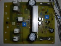
Nice work, Hari. I have posted pics of my amplifier. I have not completed it. I will be travelling on work for about two weeks. I plan to test it as soon as I get back.
First monoblock is working
Break out the champagne!
This evening I completed the initial debug of the first of two 400W/ch error-correcting monoblock unitsutilizing BUZ901/906 series lateral MOSFETS.
Operating with +/- 65V rails, the amplifier delivers a clean 400 Watts into a 4 ohm resistive load. I did not push beyond 400 watts because of power limitations of the test load. Nor have I had the chance to test into reactive loads yet. It took me about a day to track down and fix a stubborn oscillation problem. (100 pf between gate and source fixed it) Now the amp produces clean square waves with a tR/tF of approx 1.1 uS with no signs of instability.
The overcurrent circuit has paid for itself many times over during the last couple of days of debug. Each time the output stage went into oscillation, the OCP circuit reliably shut down the output stage and prevented any damage to the $200.00 worth of output transistors.
The error correction scheme utilizes a 150 MHz opamp whose rails float on the amp's output. By differencing the voltage from the driver stage and that from the amp itself, an error signal is generated. The advantage of floating the opamp is that the error voltage is directly referenced to the driver output and need only generate a few volts under worst case conditions.
All other auxiliary circuitry - inrush current limiter, thermal cutouts. speaker delay and DC cutout relays, and the error correction amplifier- all test out OK.
I'll take some pictures and post them later this weekend.
Hi quasi, there is a problem with the amp. I switched on (with a light bulb in series with the primary winding of the transformer) and there were no fireworks. I checked the output offset with a DC meter and it was hovering around 5.5mV. Then I placed the DC voltmeter across the 100ohm resistor and turned the 200ohm trimmer. But the voltmeter shows 0V no matter what the position of the trimmer. Both channels have the same problem. Where should I start looking?
Vivek
Vivek
Vivek
I know it sound silly but all the same - are you sure the fuses are still not in there? In that case the resistor will not make any difference and the voltage across it will be zero. Just a thought.
I've started testing my module. Everything was fine, I was playing music into my speakers when - BANG - two of the mosfets blew!! I'm still trying to figure out why.
Hari
Well, in that case there must be an open circuit somewhere. Zero volts means zero current. Did you check the voltage across both the resistors (+side as well as the -side)?
Hari
Hari
Another leach
An externally hosted image should be here but it was not working when we last tested it.
An externally hosted image should be here but it was not working when we last tested it.
pen said:Another leach
Hey Pen,
Nice Leach amp, but why in Quasi's NMOS amp topic? There's a separate thread (or two) for Leach amps photos.
One might say these amps are 'bipolar' opposites of each other.

..Todd
Hello all,
I finished my Nmos350 amplifier. I'm very happy because it's nice working just only small heatsink very hot (I can't touch 5 seconds). Therefore I must be use small fan. I can't say so much because my English very poor.
Thanks for design's Quasi and all of DIYer.
I finished my Nmos350 amplifier. I'm very happy because it's nice working just only small heatsink very hot (I can't touch 5 seconds). Therefore I must be use small fan. I can't say so much because my English very poor.
Thanks for design's Quasi and all of DIYer.
Attachments
And more pictures
An externally hosted image should be here but it was not working when we last tested it.
Attachments
Vuthanh,
If these huge heatsinks are getting so hot then a bias problem must there (too high bias). What's your current bias setting?
If these huge heatsinks are getting so hot then a bias problem must there (too high bias). What's your current bias setting?
Hi!
This is not amp. it is thing.
Q. where goes the hot air of heatsinks?
Is this your design or somebody help you?
Rergards zeoN_Rider
This is not amp. it is thing.
Q. where goes the hot air of heatsinks?
Is this your design or somebody help you?
Rergards zeoN_Rider
I think Thanh is refering to the small heatsink for the 2nd and 3rd stage transistors. This can be quite warm depending on the rail voltage used. The MJE340 / 350 are quite rugged though and will still dissipate 11 watts at 80 degC. This is one of the reasons they were selected. If you are concerned by this then you need to use a larger heatsink with more surface area, or use fan cooling.
Anyway Thanh, this is one of the most creative and nicest Nmos350 builds I have seen. Well done.
I do agree with Zeonrider though. The airflow for the large heatsinks is blocked by the top panel. Then maybe with heatsinks that big it does not matter, please let us know.
Finally that looks like a very heavy amp sitting on top of your other units.
Cheers
Q
Hi,
The rail voltage use +/- 53Vdc. My current bias setting is 60mA because I use 2 pair IRFP450. The Huge heatsinks very cool then small heatsinks of MJE340/350 very hot.If these huge heatsinks are getting so hot then a bias problem must there (too high bias). What's your current bias setting?
Attachments
Is this your design or somebody help you?
This is my design. And it's same tube amp?
Attachments
Hi Quasi
Thanks all.
Yes, I use small fan at back amp. I can not use larger heatsink that not enough space to do.I think Thanh is refering to the small heatsink for the 2nd and 3rd stage transistors. This can be quite warm depending on the rail voltage used. The MJE340 / 350 are quite rugged though and will still dissipate 11 watts at 80 degC. This is one of the reasons they were selected. If you are concerned by this then you need to use a larger heatsink with more surface area, or use fan cooling.
Thanks all.
Attachments
Re: First monoblock is working
This evening I completed the initial debug of the first of two 400W/ch error-correcting monoblock unitsutilizing BUZ901/906 series lateral MOSFETS...
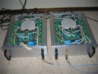
The attached image shows the two monoblock amps. Positive and negative output stages are thermally attached to the two heatsinks on either side. The (gain stage) differential, VAS, and EC, resides on a separate PCB that is attached to the front panel and is not visible. The PCB in the center foreground is for power distribution and connects to the main electrolytics as well as a pair of floating +/- 15V supplies for the EC and +/-12V supplies that boost the main supply of +/-65V to +/- 78V that supplies the gain stage. The small PCB at the back is for power management and implements inrush limiting and speaker turnon delay.
I have tested the amps up to 400W/ch into 4 ohms || with 0.5 ohm and 1 uf, withno signs of instability.
I still have to complete wiring to the input jack (that is why there is loose wiring coming out of the top). Other than that, the monoblock amps test out fine and sound great driving a pair of Snell type A speakers. All that remains is to disassemble the chassis, send it to the anodizing shop, and then put things back together.
This evening I completed the initial debug of the first of two 400W/ch error-correcting monoblock unitsutilizing BUZ901/906 series lateral MOSFETS...
The attached image shows the two monoblock amps. Positive and negative output stages are thermally attached to the two heatsinks on either side. The (gain stage) differential, VAS, and EC, resides on a separate PCB that is attached to the front panel and is not visible. The PCB in the center foreground is for power distribution and connects to the main electrolytics as well as a pair of floating +/- 15V supplies for the EC and +/-12V supplies that boost the main supply of +/-65V to +/- 78V that supplies the gain stage. The small PCB at the back is for power management and implements inrush limiting and speaker turnon delay.
I have tested the amps up to 400W/ch into 4 ohms || with 0.5 ohm and 1 uf, withno signs of instability.
I still have to complete wiring to the input jack (that is why there is loose wiring coming out of the top). Other than that, the monoblock amps test out fine and sound great driving a pair of Snell type A speakers. All that remains is to disassemble the chassis, send it to the anodizing shop, and then put things back together.
Attachments
- Home
- Amplifiers
- Solid State
- Power amp under development