@joel & rlg,
thanks for the inputs! I'll look for Newport when I get to the place soon for my quasi parts and to Alexan for the pcb.
for the 0.1uF MKT, I found Cherubim (along Ronquillo) selling this cap, when I was building my Mauro's MyRevC GC.
-joeyg
thanks for the inputs! I'll look for Newport when I get to the place soon for my quasi parts and to Alexan for the pcb.
for the 0.1uF MKT, I found Cherubim (along Ronquillo) selling this cap, when I was building my Mauro's MyRevC GC.
-joeyg
Re: 33ohms or 39 ohms?
For R9 yu can use either one, it's not that important.
Mylar will be fine, as long as the voltage rating is ok.
Cheers
Q
jhoel47 said:Hi Quasi
Question about R9 , layout it was 39ohms ,but in schematics it was 33 ohms , which one should I follow?
Can I use Mylar cap in place of .1uf MKT cap? Its not available in local electronics supply here.
Thanks for your reponds.
Joel
For R9 yu can use either one, it's not that important.
Mylar will be fine, as long as the voltage rating is ok.
Cheers
Q
Cool Power Switch
I found these awesome looking switches but they are momentary, no good for amps. 🙁 Then I thought if Quasi needs 24V for protection circuit, why not use the 24V to set up a momentary on/off cicuit? I just love the look and feel of these switches. So...
I found these awesome looking switches but they are momentary, no good for amps. 🙁 Then I thought if Quasi needs 24V for protection circuit, why not use the 24V to set up a momentary on/off cicuit? I just love the look and feel of these switches. So...
Attachments
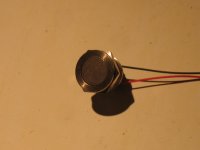
 It was a work in progress...
Re: Re: 24 Volt Supply with momentary circuit
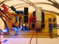
Everybody seems to be getting along well together. The momentary control circuit on the board should be flipped so the relay's contacts are in line with the other AC Lines I went and routed the AC power around the PCB to the relay. Also it may be better to build a larger board and include a soft start cicuit. It is not really required as the XFMR for each channel is 400VA and they will be turned on seperate from each other.
Now where are those Toshiba Devices...
I am learning as I go along here and I hope you folks find it useful to see these things?
Cheers,
Shawn.
Everybody seems to be getting along well together. The momentary control circuit on the board should be flipped so the relay's contacts are in line with the other AC Lines
I went and routed the AC power around the PCB to the relay. Also it may be better to build a larger board and include a soft start cicuit. It is not really required as the XFMR for each channel is 400VA and they will be turned on seperate from each other. Now where are those Toshiba Devices...
I am learning as I go along here and I hope you folks find it useful to see these things?
Cheers,
Shawn.
Attachments

Tom,
Thanks for sharing this idea. I'll consider about adding momentary sw when I get to this section.
Thanks for sharing this idea. I'll consider about adding momentary sw when I get to this section.
12volts relay
Hello Quasi ,
Good day, only got 12volts relay for both DC protect and softstart, please send me the schematics for using 12volts relay, thanks a lot man.
joel
Hello Quasi ,
Good day, only got 12volts relay for both DC protect and softstart, please send me the schematics for using 12volts relay, thanks a lot man.
joel
BC546 ?
GUYS
BC546 is TO-92 casing style, I saw in picture T8 bc546 is TO-126 (t8 that suppose to be mounted on the main heat sink) , TO-92 dont have screw hole, is there a type of TO-126 of BC546 transistor? or use TO-92 BC546 and find other way of mounting it to heat sink?or is there a replacements for T8 ? Thanks ..
joel
Hi,
you could superglue the To92 to the heatsink,
or
drill a hole in the sink and insert the To92 into it with thermal compound bath to transfer the heat.
or
bend an aluminium clamp and bolt the To92 to the sink.
or
try (impossible) to find a To126 transistor with similar specs to the BC546.
or
ask Quasi if any of the spec can be relaxed?
Re: BC546 ?
This link http://www.diyaudio.com/forums/showthread.php?postid=800468#post800468 shows a picture of how I mounted T8 on my board. It mounts underneath the PCB and into a hole drilled in the heatsink. Accuracy is a must here. Others have substituted T8 with a TO126 transistor mounted seperately on the heatsink and used fly leads back to the PCB. If you do this please check the pin-outs.
Cheers
Q
jhoel47 said:GUYS
BC546 is TO-92 casing style, I saw in picture T8 bc546 is TO-126 (t8 that suppose to be mounted on the main heat sink) , TO-92 dont have screw hole, is there a type of TO-126 of BC546 transistor? or use TO-92 BC546 and find other way of mounting it to heat sink?or is there a replacements for T8 ? Thanks ..
joel
This link http://www.diyaudio.com/forums/showthread.php?postid=800468#post800468 shows a picture of how I mounted T8 on my board. It mounts underneath the PCB and into a hole drilled in the heatsink. Accuracy is a must here. Others have substituted T8 with a TO126 transistor mounted seperately on the heatsink and used fly leads back to the PCB. If you do this please check the pin-outs.
Cheers
Q
Quasi,
thanks for your replay man good idea .About 12 volts relay, I will be using 12 volts relay since this is what I only got, please send me the schematics modification for both DC protect and softstart,,, thank you very much ..
joel
my address joel_m@pimes.com.ph
thanks for your replay man good idea .About 12 volts relay, I will be using 12 volts relay since this is what I only got, please send me the schematics modification for both DC protect and softstart,,, thank you very much ..
joel
my address joel_m@pimes.com.ph
jhoel47 said:Quasi,
thanks for your replay man good idea .About 12 volts relay, I will be using 12 volts relay since this is what I only got, please send me the schematics modification for both DC protect and softstart,,, thank you very much ..
joel
my address joel_m@pimes.com.ph
You can run the the circuits as they are with a 12 volt relay by using 12-14 volt rails. The switching times will increase but they can be reduced again by reducing the value of the timing capacitors.
Or you can run everything on 24 volts and just put a resistor in series with the relay. The value of the resistor should be the same as the resistance of the relay coil (or slightly less). This can be done for all the relays you use..
Cheers
Q
Hi Quasi !
Great project !
Sorry but, I not understand the value of Q1 Q2 Q3 Q4 Q5 and the model of 24V relay in dc detect ....
Please retry to me ...
grechejr@gmail.com
thank you !!!
Great project !
Sorry but, I not understand the value of Q1 Q2 Q3 Q4 Q5 and the model of 24V relay in dc detect ....
Please retry to me ...
grechejr@gmail.com
thank you !!!
grechejr said:Hi Quasi !
Great project !
Sorry but, I not understand the value of Q1 Q2 Q3 Q4 Q5 and the model of 24V relay in dc detect ....
Please retry to me ...
grechejr@gmail.com
thank you !!!
Hi grechejr
I have sent you some mail. The value of these transistors is shown in the DC detect circuit schematic that is contained in the document I sent you. Because the DC detect circuit is built on the same board as the amplifier I have used Q instead of T for the transistors to show the seperation between the sections.
The relay you need is a single pole double throw (SPDT) with contacts rated at 10 amps minimum with a 24 volt coil. The style I have chosen is probably the most popular in the world, is made by many manufacturers and available at most electronics stores. If you take your PCB with you, you can make sure it fits.
Cheers
Q
hi all maker of quasi amp,
does anyone try to connect this amp into bridge mode? how's it sound, and how much the power capacity @8omhs.
rlg.😉 😉 😉
does anyone try to connect this amp into bridge mode? how's it sound, and how much the power capacity @8omhs.
rlg.😉 😉 😉
Bridged Quasi
No I have not tried to bridge my Quasi amp. I would be affraid unless I had a huge array of speakers connected correctly.
Shawn.
rlg_200 said:hi all maker of quasi amp,
does anyone try to connect this amp into bridge mode? how's it sound, and how much the power capacity @8omhs.
rlg.😉 😉 😉
No I have not tried to bridge my Quasi amp. I would be affraid unless I had a huge array of speakers connected correctly.
Shawn.
quasi & tomwaits,
can u post the technical data (specification) of ur amp.
damping factor=?
thd+n=?
input sensitivity=?
input impedance=?
ouput impedance=?
rlg.😉 😉 😉
can u post the technical data (specification) of ur amp.
damping factor=?
thd+n=?
input sensitivity=?
input impedance=?
ouput impedance=?
rlg.😉 😉 😉
Hi Quasi, TomW and Rig,
do not bother with damping factor and distortion specs. They are irrelevant to the sound/quality of a feed back solid state amplfier.
Output impedance might be useful to some at a selection of frequencies.
Rig,
if you knew this what would you do with the information? I don't know how to interpret it.
- Home
- Amplifiers
- Solid State
- Power amp under development