If your cross over network is passive, Try to change in active in 24dB rolloff to improve your bass.
Power supplies
I dropped 10ohms on each rail simultaneously on one toroidal. I measured 39VDC , 10R , I=3.9Amps
That’s 152 watts DC RMS per rail...I need two rails per channel which says I have near the capacity of 300 watts RMS of supply available per channel of an amp(without clipping) I was needing something like 230 watts to drive 2ohms so this thing will deliver some huge Kick *** Q!
How do I calculate soar, can you guys (Q, Andrew) share some spreadsheet action?
My momentary start circuit got working today and I was debating a small soft start circuit as well? The deluxe Quasi(s) are coming...
Cheers,
Shawn.
Hi Quasi,
Let me explain my thoughts and you can come back and justify your statement.
Reactive loads stress the output stages much more than resistive loads.
An output stage that can drive a 4r resistive load is not necessarily suitable for driving a 4ohm speaker. The reactance of the speaker can take the output semis outside the temperature corrected SOAR, particularly for sustained low frequency signals at maximum output voltage.
An amplier that can drive a 4ohm reactive load at greater than 45degree phase angle can probably drive most 4ohm speakers and a 60 degree phase angle will allow driving into almost any difficult 4ohm speaker.
A further test of the output stage that can be used as a goodness indicator is the ability of the amp output stage to drive a resistive load that is LOWER than the speaker load.
I have found that IF the amp output stage can safely (remain inside the temperature corrected SOAR) drive a resistive load of about half the intended speaker impedance then the output stage will perform well into demanding speakers.
So my testing procedure is check the temperature corrected SOAR for a 60degree phase angle reactive load of the same impedance of the intended speakers.
Repeat the SOAR check for a resistive load = half the speaker impedance.
Test the amplifier into BOTH those loads upto clipping. If it passes then it will drive any domestic speaker from the tested impedance upwards. i.e. test into 2r and play into 4ohms. note r indicates resistive and ohms indicates reactive. If IV limiting is installed it should not activate on either of these tests (although it may be appropriate for triggering ~95% of clipping voltage).
This is completely the opposite of your statement.
There is one important caveat.
The testing must be carried out at device temperatures that do not exceed the SOAR temperatures assumed in the earlier design stages.
This demands short testing (two or three seconds) and long cooling periods (thirty seconds or more) to ensure the heatsinks mimic operating and design temperatures. This same temperature philosophy applies just as well to PA amps the only change being that the testing time can be much extended provided the design temperatures are not exceeded.
I do not agree.50 volt rails you could easily drive into 2 ohms speakers and get around 400 watts. (HiFi only, for testing do not go below 4 ohms).
Let me explain my thoughts and you can come back and justify your statement.
Reactive loads stress the output stages much more than resistive loads.
An output stage that can drive a 4r resistive load is not necessarily suitable for driving a 4ohm speaker. The reactance of the speaker can take the output semis outside the temperature corrected SOAR, particularly for sustained low frequency signals at maximum output voltage.
An amplier that can drive a 4ohm reactive load at greater than 45degree phase angle can probably drive most 4ohm speakers and a 60 degree phase angle will allow driving into almost any difficult 4ohm speaker.
A further test of the output stage that can be used as a goodness indicator is the ability of the amp output stage to drive a resistive load that is LOWER than the speaker load.
I have found that IF the amp output stage can safely (remain inside the temperature corrected SOAR) drive a resistive load of about half the intended speaker impedance then the output stage will perform well into demanding speakers.
So my testing procedure is check the temperature corrected SOAR for a 60degree phase angle reactive load of the same impedance of the intended speakers.
Repeat the SOAR check for a resistive load = half the speaker impedance.
Test the amplifier into BOTH those loads upto clipping. If it passes then it will drive any domestic speaker from the tested impedance upwards. i.e. test into 2r and play into 4ohms. note r indicates resistive and ohms indicates reactive. If IV limiting is installed it should not activate on either of these tests (although it may be appropriate for triggering ~95% of clipping voltage).
This is completely the opposite of your statement.
There is one important caveat.
The testing must be carried out at device temperatures that do not exceed the SOAR temperatures assumed in the earlier design stages.
This demands short testing (two or three seconds) and long cooling periods (thirty seconds or more) to ensure the heatsinks mimic operating and design temperatures. This same temperature philosophy applies just as well to PA amps the only change being that the testing time can be much extended provided the design temperatures are not exceeded.
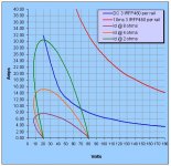
The chart attached shows the load lines for reactive 8,4 and 2 ohms typical speakers with a worst case scenario of current being 45 degrees out of phase with the voltage (Vds).
The modelling does not assume stable 8,4 and 2 ohm resistances and this explains the peak current of over 30 amps for the 2 ohm load instead of the expected 25 amps.
The 3 load curves are compared to the blue and red SOAR curves (derated for 50 deg C). The chart shows that the 2 ohm load line exceeds the DC SOAR but is well inside the 10mS SOAR.
Whilst I am comfortable with this load capability in domestic situations remember also that the best (and reasonable) power supply will still drop around 5% and this makes for extra comfort.
I note that testing an amp into 2 ohms (sine wave & several seconds) would be risky but this scenario never happens in music content. Having said that, most (all?) people bench test amps into resistive loads and with a 2 ohm resistive load the load line just crosses the derated DC SOAR (not shown here). So under typical "test" conditions the amp will be fine.
My $0.02
Cheer
Q
Attachments
Having re-read your post Andrew (3 times I think) I would like to add that bass guitarists should not follow my power selection guide and should only go by the DC SOAR load line comparison. The Quasi however was never intended as a musical instrument amplifier, dare I say it's too good?
Cheers again
Q
Cheers again
Q
Hi Quasi,
your explanation almost reached the same conclusion as mine.
But your logical analysis stopped just short of the correct answers.
A 4ohm reactive load that takes the output stage to just inside the Tc50 SOAR should be safe for most 4ohm speakers. You should be able to test your amplifier into a simulated (45degree) reactive load and provided one takes care to avoid exceeding the Tc<50degC condition the amp should always survive.
Are we agreed on this first point?
We may disagree about whether DC, 1Second, 100mS or 10mS SOA be used to define our safe limits. We leave that one to production/long term testing.
Now consider the 2r resistive load. You have not drawn the 2r load line but just like the 4ohm reactive falls on the same (safe) side of the Tc50 SOAR. This implies that the amplifier can be tested in the same temperture controlled manner as was applied to the 4ohm reactive load.
I use 60degree phase angle and for my situation the 2r load is much LESS stressfull than the 4ohm 60degree load. For your 45degree 4ohm load the 2r load is slightly less stressfull than the 4ohm load.
The advantage of the half resistance test is loading and current testing of the PSU, cabling, connections and fuses and moves closer to the short circuit condition to prove the amp won't blow up when abused. Close rated line fuses will probably blow in this test, but that just proves one has selected the correct fuse rating.
I have (still) not yet found my safe method of testing protection triggering into near zero r loads. Sidetracked by other projects/work.
I agree you comments on PA type amps. They are the same design problem, one simply has to select the criteria to suit the duty.
Re: MY 1st PCB for QUASI AMP
Looking good but don't forget to scrub off the remaining photo resist...its the blue/green stuff on top of the copper. You should be looking at shiny copper traces by now. I use medium steel wool to scrub my boards but many people find it TOO harsh so they use coarse scrubbing pads...as you were.
More Quasi in the oven! I like it. 😀
Shawn.
jhoel47 said:My friend manage to find the photo etch PCB in manila...
Looking good but don't forget to scrub off the remaining photo resist...its the blue/green stuff on top of the copper. You should be looking at shiny copper traces by now. I use medium steel wool to scrub my boards but many people find it TOO harsh so they use coarse scrubbing pads...as you were.
More Quasi in the oven! I like it. 😀
Shawn.
@joel,
can you share the store name where you bought your photoetched pcb and the price? Also, where did you buy your quasi parts? There are so many fake parts being sold out there and its so hard to distinguish which shops sell good/original parts. thanks. -joeyg
can you share the store name where you bought your photoetched pcb and the price? Also, where did you buy your quasi parts? There are so many fake parts being sold out there and its so hard to distinguish which shops sell good/original parts. thanks. -joeyg
Easy Way of PCB etching.
You can print out with HP laser jet on earth paper.( mirror )
I already tested with HP laser Printer.
And then iron on PCB.
and then put in water a few hours, rub with teeth brush gently ( becareful ).
U can correct error on that PCB with permenent pen.
And then ...........
That is very easy way.
Sorry for my poor english.
VOLKS77,
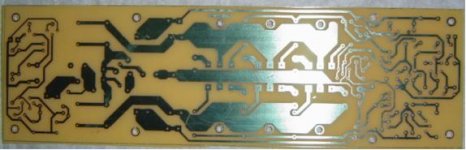
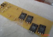
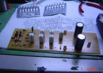
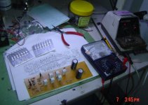
Yesterday my friend went in RAON (manila)I ask him to look for photo etch PCB he found it in ALEXAN RAON worth php170 size 5X10 inch, other parts are all pasive components , no irfp450 yet still i have to buy but I have 2sk1530 here , attached is a partial inserted and soldered parts, more to come..
joel
Attachments

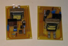
Power Supplies
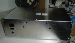
I made some 24 volt power supplies for Quasi. I included a momentary Flip-Flop circuit for my momentary power switch. Also, I included board-level fuses for the main XFMR and the sub XFMR. Oh yeah, and the LED resistor and connector are on there too.😀
BTW, nice case Joel! You are fast! You will beat me in the race for the next Quasi! You make lots of posts to the thread, I like that...It reminds me of...bla bla bla ...me.
Cheers,
Shawn.
Attachments
Re: SOAR
Oi...Mr T, where's my spreadsheet?
TomWaits said:Thanks Mr. T for the XL spread sheets.
Cheers,
Shawn.
Oi...Mr T, where's my spreadsheet?
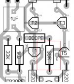
33ohms or 39 ohms?
Hi Quasi
Question about R9 , layout it was 39ohms ,but in schematics it was 33 ohms , which one should I follow?
Can I use Mylar cap in place of .1uf MKT cap? Its not available in local electronics supply here.
Thanks for your reponds.
Joel
Hi Quasi
Question about R9 , layout it was 39ohms ,but in schematics it was 33 ohms , which one should I follow?
Can I use Mylar cap in place of .1uf MKT cap? Its not available in local electronics supply here.
Thanks for your reponds.
Joel
Attachments
- Home
- Amplifiers
- Solid State
- Power amp under development