But a 80V-CT transformer ( > ~400VA) gives 5% higher voltage when only loaded by the rectifier circuit (diodes + cap bank [+ bleeder]). That means (40×1.05×1.4)-1.2 = 58V.
So AndrewT's 58V seems to be right for me.
So AndrewT's 58V seems to be right for me.
sixtek said:But a 80V-CT transformer ( > ~400VA) gives 5% higher voltage when only loaded by the rectifier circuit (diodes + cap bank [+ bleeder]). That means (40×1.05×1.4)-1.2 = 58V.
So AndrewT's 58V seems to be right for me.
I have just fired up a 700VA 52 Vac XFMR and it measures 72.5 Vdc with power supply at idle. My math is dead on.
Your formula is not the one I use and mine always gives real world results. Oh well, mine works for me. 🙂
BTW did you bench the reading or are you too just calculating it? Check it out in the real world. Is it possible there is some other unknown factor?
Cheers,
Shawn.
sixtek said:But a 80V-CT transformer ( > ~400VA) gives 5% higher voltage when only loaded by the rectifier circuit (diodes + cap bank [+ bleeder]). That means (40×1.05×1.4)-1.2 = 58V.
So AndrewT's 58V seems to be right for me.
One might be talking about voltage at rated VA and the other actual idle voltage. By the way why do you subtract 1.2 ?
Cheers
Q
Hi Quasi,
The 1.2 V is an approximation of a bridge rectifier voltage drop at low current. I do the same thing. Actual reading will vary depending on the regulation factor of the transformer and a ton of other things, as you well know. 😉
-Chris
The 1.2 V is an approximation of a bridge rectifier voltage drop at low current. I do the same thing. Actual reading will vary depending on the regulation factor of the transformer and a ton of other things, as you well know. 😉
-Chris
anatech said:Hi Quasi,
The 1.2 V is an approximation of a bridge rectifier voltage drop at low current. I do the same thing. Actual reading will vary depending on the regulation factor of the transformer and a ton of other things, as you well know. 😉
-Chris
I agree Chris, but not at low current. Only 0.6v should be calculated here. At higher current it might rise to a volt or so, but this is more useful when calculating max power.
Cheer
Q
quasi said:
I agree Chris, but not at low current. Only 0.6v should be calculated here. At higher current it might rise to a volt or so, but this is more useful when calculating max power.
Cheer
Q
I calculate .7 volt drop across PN junctions in diodes and of course 1.4 for bridge rectifiers and 1.414 gives me the RMS value in DC. My measurements and calculations have been within a 1 volt variance since 1988!
 Is there something wrong with this? I can't figure the error if the digital multi-meter and/or oscilloscope I have are always backing me up.
Bench it. That is where you find the real truth. After the math is done, nothing compares like a real world measurement to set the record straight...sometimes😉
I will post pics if anyone wants to dispute my measurements. I have many a XFMR lying around.
This is getting off topic for our Q thread, so fire up a new one if you think I'm talking bollocks.
Cheers,
Shawn.
Off topic? ...a bit I guess. My point is that even in a brdge rectifier the AC waveform only passes through one PN junction so we should only be allowing 0.6. Petty I suposse...ok back to amps.
I guess if your within a volt it don't matter. I'm so slack I just measure the unloaded AC voltage and multiply by 1.4
Q
I guess if your within a volt it don't matter. I'm so slack I just measure the unloaded AC voltage and multiply by 1.4
Q
To get in the ballpark for loaded stereo amp supplies, just multiply the nominal unloaded trafo voltage x 1.33. Worked always. Never had to return a toroid.
quasi said:Off topic? ...a bit I guess. My point is that even in a brdge rectifier the AC waveform only passes through one PN junction so we should only be allowing 0.6. Petty I suposse...ok back to amps.
I guess if your within a volt it don't matter. I'm so slack I just measure the unloaded AC voltage and multiply by 1.4
Q
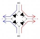
In a Full bridge rectifier the AC flows through two PN junctions in the top half of one cycle, then shifts 180 degrees to be rectified by the other two PN junctions on the other side of the cycle. WOW! I’m amazed at this point. At one time it was all moot to me. I guess I have some AC to DC intelligence that no others have? 😕 I can't go on believing that?
Get out yer' RMS DMM’s and verify. I can't be the only person to have this knowledge/experience?
On topic it is Q, as you permit.
Jah,
Shawn.
An example:
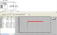
A 2X45VAC nominal 625 VA toroidal with 7% regulation delivers 2x60VDC after bridge rectification when loaded to 1/3 of its nominal current ability. Good assumption for energetic music average when fully driven. During prolonged peaks the system will sag more but only momentarily, and it has been psychoacoustically proven that the compression effect gives subjectively a louder impression before audible clip vs stiff supplies.
A 2X45VAC nominal 625 VA toroidal with 7% regulation delivers 2x60VDC after bridge rectification when loaded to 1/3 of its nominal current ability. Good assumption for energetic music average when fully driven. During prolonged peaks the system will sag more but only momentarily, and it has been psychoacoustically proven that the compression effect gives subjectively a louder impression before audible clip vs stiff supplies.
Attachments
salas said:An example:
A 2X45VAC nominal 625 VA toroidal with 7% regulation delivers 2x60VDC after bridge rectification when loaded to 1/3 of its nominal current ability.

Now we are talking turkey, but can you back the "load" off to show these folks what a "semi" loaded power supply looks like after rectification with just a cap bank, a by-pass cap & bleeder resistor? I suggest PSU Designer II...and it is free to download and use for non-commercial applications.
Cheers,
Shawn.
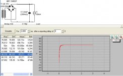
salas said:Say with 50ma load? Momento.
Sounds good. Is this program you have available to all?
Cheers,
Shawn.
TomWaits said:
Sounds good. Is this program you have available to all?
Cheers,
Shawn.
Yes, every tubehead like me uses it. Here
salas said:Its 66VDC for 50mA. Column diff. But why you care? Loaded working amp is the goal.
Really I don't care. 😀 I have my method and my method is true. BTW, I think PSU Designer gave me accurate results. Not that it is the bible either.
One more time for full bridge recifiers:
(Vac x 1.414)- 1.4= Vdc RMS. It is bullet proof for me.
Cheers,
Shawn.
There is a small degree of uncertainty not intrinsic to simulation but to claimed regulation and nominal voltage toroid manufacturer quotations. For such a class of a PSU it takes about 16 transistors (stereo) to drag it down from its unloaded overvoltage to your calcs for 50mA bias each for our example. Practically you are dead on. That is what the user is going to experience on the DVM's LCD when biasing the amp.
Hi,
Tom your formula is absolutely spot on, IF the Vac is the actual open circuit voltage measured at the transformer @ the mains supply voltage coming in at that time.
I can see why you get the wrong results and why you cannot see where we are coming from.
It is down to using a non fixed mains supply voltage and ignoring transformer regulation.
A transformer in the UK is specified at a fixed supply voltage and output voltage at the rated output current.
Change the supply voltage and/or the output current and the output voltage and of necessity the smoothed and rectified DC voltage must also vary.
Quasi,
the bridge rectifier across a pair of secondaries with the centre tap to the 0v common shows just one diode drop to each half of the dual polarity supply. i.e. two diode drops to the whole dual polarity supply voltage.
Anatech,
agreed, at low currents the diode voltage can fall to nearer 0.55v and rise as high as 1v at high currents.
- Home
- Amplifiers
- Solid State
- Power amp under development