sixtek said:Baskiria,
Check this post, you'll find there everything: schema, PCB, etc...
http://www.diyaudio.com/forums/showthread.php?postid=1103559#post1103559
or, if you send me an email I will reply with a pdf containing all the details.
Cheers
Q
Quasi! i sent you an email i don't know if you got it, i want to know if you can email me the lastes schematic/pcb/tracks for the Nmos350 amp, since i want to build it. And one thing, what's the 24v relay for!? i can't figure it out.
my email is hernanmcarg@hotmail.com
my email is hernanmcarg@hotmail.com
Hi Quasi,
im new in diyaudio, came thanks to friend who build your amp (vodoochild was and still his name) and recomend your amp as one of the best documented and one of the best around, and from what im reading he was right.
i read the latest post and found the links for schem and stuff but as you offer to send them... well, "el pez por la boca muere".
Im goin from gainclone builder to solid state, i hope not get hurt (and i mean it).
hope some feedback "chau"
email: spektorj80@yahoo.com.ar
hernanstafe said:Quasi! i sent you an email i don't know if you got it, i want to know if you can email me the lastes schematic/pcb/tracks for the Nmos350 amp, since i want to build it. And one thing, what's the 24v relay for!? i can't figure it out.
my email is hernanmcarg@hotmail.com
The relay is part of a DC detection and protection circuit. Both the amp and protection circuit are on one board. I'm at work now, so tonight I will email the document which also shows the DC detection schematic. Then it will make sense.
Juan Spektor said:Hi Quasi,
im new in diyaudio, came thanks to friend who build your amp (vodoochild was and still his name) and recomend your amp as one of the best documented and one of the best around, and from what im reading he was right.
i read the latest post and found the links for schem and stuff but as you offer to send them... well, "el pez por la boca muere".
Im goin from gainclone builder to solid state, i hope not get hurt (and i mean it).
hope some feedback "chau"
email: spektorj80@yahoo.com.ar
I'll email the document to you tonight when I get home. It's good to read about Voodoochild's amp working well. Good luck with your build.
Cheers
Quasi
hey Quasi, thanks a lot, i'm anxiously waiting for that mail, since i want to build that amp really bad, it seems to be great, and i'm sure it performs in an outstanding way. I also want to ask something out of the subject, are you an electronics engeneer or something? because i'm beginning electronics engeneering in college and i wonder if someday i'll be able to design stuff like this!!
Thanks again!
Thanks again!
Actually I'm an engineers worst nightmare.....that's right I'm in sales & marketing.
I did however start my working life as an electronics technician and have always had an interest in electronics, particularly in audio and power control. My only "official" commercial endeavour was designing, manufacturing and of course selling power control systems for trucks and coaches (luxury buses). This included alternator regulators, DC-AC inverters & DC-DC converters.
When you complete your engineering education designing stuff like this should be a breeze.
Cheers
Q
thanks quasi for your time, btw how did you ended in marketing, being such a good designer, imagine if you were an engeneer!.
better this way otherwise i probably be in the gainclon side 😉
HI there "hernanstafe" nice to have some fellow compatriot to talk,
where you study? im in unviersidad de la patagonia in
comodoro rivadavia.
Well, time to wait for my mailman.
(sorry my bad english)
better this way otherwise i probably be in the gainclon side 😉
HI there "hernanstafe" nice to have some fellow compatriot to talk,
where you study? im in unviersidad de la patagonia in
comodoro rivadavia.
Well, time to wait for my mailman.
(sorry my bad english)
Quasi, thanks a lot for your help and for the email, i'll start working on the amp right away, i can't wait to see it working!!it'll take some time tho because the fets are rather expensive here. I agree with Spektor when he says you should have gone for engeneering, you already are an EXCELLENT amp designer tho, i wish someday i can get to do this stuff.
Anyways i have 3 questions about the amp. The first one, how do i do the impedance, the 4uH one, cause i think you can't buy those? can you tell me how to build it?
Are the fets isolated from the heatsink?
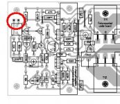
And the last one, in the pcb, in the upper left corner there are 2 pinouts without any marks, what are those? ground or what? I attach to the msg a picture of the pins i'm talking about.
Again, i can't thank you enough for your help, and congratulate you for this masterpiece you've created.
Anyways i have 3 questions about the amp. The first one, how do i do the impedance, the 4uH one, cause i think you can't buy those? can you tell me how to build it?
Are the fets isolated from the heatsink?
And the last one, in the pcb, in the upper left corner there are 2 pinouts without any marks, what are those? ground or what? I attach to the msg a picture of the pins i'm talking about.
Again, i can't thank you enough for your help, and congratulate you for this masterpiece you've created.
Attachments
Thanks Black_Chicken. Now i was wondering if anyone had a good preamp to use with this project. I bought a preamp kit a while ago but it's not so good because it doesn't have much gain, so it's pretty much worthless, except for the volume and tone controls. I was looking for a good pream, with good quality sound and good gain, i'm going to use this amp and the pream to make a subwoofer so if it doesn't have any tone controls is good to me. Thanks a lot guys!!
Thanks a lot for the mail, im now go to bed
Quasi (or any who knows) what are the specifications of the amp and how much input need to drive it at full.
Quasi (or any who knows) what are the specifications of the amp and how much input need to drive it at full.
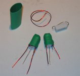
hernanstafe said:... how do i do the impedance, the 4uH one, cause i think you can't buy those? can you tell me how to build it?
Q is not too fussy about the exact value of the 4uH coil on the output as long as it is close. I googled an online inductor calculator to give me the approximate turns and wire length/gauge for a 1 cm core, in my case the 5watt resistor was the core size. I thought I had the page book-marked but I can't find it.😡
Perhaps the picture will help? Q uses a plastic bobbin for his inductor.
Cheers,
Shawn.
Attachments
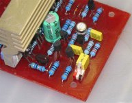
hernanstafe said:Are the fets isolated from the heatsink?
If you use "regular" FETs you will require an insulated pad and/or grease of some sort. I think there are FETs with isolated tabs that do not require the insulation pad but heat sink grease is still required for this type of package. Some folks use "rubber" type pads to insulate the tab without heat sink grease. So many options...
... in the pcb, in the upper left corner there are 2 pinouts without any marks, what are those? ground or what? I attach to the msg a picture of the pins i'm talking about.
As Black_Chicken said, they for the input signal. The pin that goes directly to C1 is the positive.
Good Luck and happy building! BTW technical people make great sales and marketing folks as they can talk the talk and walk the walk. shhhhh...sometimes they make more money than engineers but don't say that too loud around here.🙂
Cheers,
Shawn.
Attachments
Regarding the output coil;
I wound 30 turns of 1mm wire on a bobbin 1cm in diameter x 1 cm in height. It worked out to 3 layers of 10 turns. As Shawn mentioned the exact value is not critical.
Indeed I moved to the dark side for the money.....
Cheers
Quasi
I wound 30 turns of 1mm wire on a bobbin 1cm in diameter x 1 cm in height. It worked out to 3 layers of 10 turns. As Shawn mentioned the exact value is not critical.
Indeed I moved to the dark side for the money.....
Cheers
Quasi
Side tracked . . .
sigh...
Building amplifiers are no different from programming. When you start working, there's always something to do first. And when you start working on that, the same feeling arises also.
I am now working on my UV Exposure Box for processing my Photo-PCB. Then, I will need to work on my Etching system. And then, I will start soldering parts into my n-Mos 200-T220 PCB.
But don't get me wrong, I am not complaining, I am enjoying every minute of the project.
😀
Specifications of Amp
Juan,
I have been working on collecting the amp specifications into a set of links that I will put in a posting. I have been stalled in that effort as some personal matters of a demanding nature yet again.
That said you will find "specifications" of this amp are basic as there are different variables due to the ease of the parts and power supply designs that builders can choose. It is this parts flexibility that makes this stable design so popular.
In answer to your question about how much input is needed to drive the amp to full power is actually a very basic and subjective discussion. You will find in this thread more than a few discussions about power supply design and SOA of output devices for the rated impedence vs actual load the output stage will see.
The gain if the NMOS350/500 is set at 33 per R17/R18 (33K0/1K0). You can then work backwards or forwards to determine the input signal required to drive the amp to full load.
Be aware that there are losses from the supply rails that the output stage actually sees due to various elements. So as an example with +-75 V DC rails, there can be a loss of about 12-17 V DC.
For the sake of this example I will use the effective rail voltage of +- 60 V DC. To work backwards Rail/gain=input level to drive at full Peak to Peak, not RMS, therefore 60/33=1.81818181V Peak to Peak. To convert to RMS divide the P-P by the Square Root of 2 which results in 1.2856 V RMS input signal.
Assuming a pure 8 ohm output impedance the P-P Power would be 225 W P-P, and 112.5 W RMS, again assuming effective +-60 V Rails. Understand no amp should be driven to rull rated power and all music has a Peak-Peak character. The amount of P-P and sustained power levels will of course depend on the type of music you listen to, speaker load, efficiency, passive crossover or active crossover, etc.
Generally for speaker loads one designs to 4 ohm resistive for a 8 ohm rated speaker. A divide by 2 rule in general. Organ, rock music is mucc more demanding on amplifier power and supply demands. Classical music has a very wide dynamic range and therefore needs much more P-P headroom factored into the design.
If you wish to change the amplifier gain I would think it is not appropriate to increase the gain of this design. Most source signals are not going to produce more than 2 V P-P. If you reduce the gain bear in mind R17 should equal R3 for the lowest DC offset. This is important as channging R3 will affect the input corner frequency, perhaps in a significant way to impact the performance of the amplifier. Changing R18 has impact as well to the feedback loop due to the association with C7. Care needs to be taken if you wish to change any of these interdependant values.
If you are patient and search the thread you will find additional information on how the power handling and SOA are determined. If you follow the quasi power chart for supply voltage, number of output devices, speaker impedance and power supply voltage you will have a stable amplifier. The key is to be certain about your speaker impedance you expect the amplifier to be used with. The capacitance reserve of the power supply will also be a factor in the P-P and RMS handling of the amplifier assuming all else well chosen for the power level and reserve needed.
Regards,
John L. Males
Willowdale, Ontario
Canada
14 March 2007 23:20
14 March 2007 23:29 Typo correction. jlm
P.S. Quasi, I have seen at times the flag of Greece for your profile rather than the usual Aussie flag. Are you Greek or in Greece?
Juan Spektor said:Thanks a lot for the mail, im now go to bed
Quasi (or any who knows) what are the specifications of the amp and how much input need to drive it at full.
Juan,
I have been working on collecting the amp specifications into a set of links that I will put in a posting. I have been stalled in that effort as some personal matters of a demanding nature yet again.
That said you will find "specifications" of this amp are basic as there are different variables due to the ease of the parts and power supply designs that builders can choose. It is this parts flexibility that makes this stable design so popular.
In answer to your question about how much input is needed to drive the amp to full power is actually a very basic and subjective discussion. You will find in this thread more than a few discussions about power supply design and SOA of output devices for the rated impedence vs actual load the output stage will see.
The gain if the NMOS350/500 is set at 33 per R17/R18 (33K0/1K0). You can then work backwards or forwards to determine the input signal required to drive the amp to full load.
Be aware that there are losses from the supply rails that the output stage actually sees due to various elements. So as an example with +-75 V DC rails, there can be a loss of about 12-17 V DC.
For the sake of this example I will use the effective rail voltage of +- 60 V DC. To work backwards Rail/gain=input level to drive at full Peak to Peak, not RMS, therefore 60/33=1.81818181V Peak to Peak. To convert to RMS divide the P-P by the Square Root of 2 which results in 1.2856 V RMS input signal.
Assuming a pure 8 ohm output impedance the P-P Power would be 225 W P-P, and 112.5 W RMS, again assuming effective +-60 V Rails. Understand no amp should be driven to rull rated power and all music has a Peak-Peak character. The amount of P-P and sustained power levels will of course depend on the type of music you listen to, speaker load, efficiency, passive crossover or active crossover, etc.
Generally for speaker loads one designs to 4 ohm resistive for a 8 ohm rated speaker. A divide by 2 rule in general. Organ, rock music is mucc more demanding on amplifier power and supply demands. Classical music has a very wide dynamic range and therefore needs much more P-P headroom factored into the design.
If you wish to change the amplifier gain I would think it is not appropriate to increase the gain of this design. Most source signals are not going to produce more than 2 V P-P. If you reduce the gain bear in mind R17 should equal R3 for the lowest DC offset. This is important as channging R3 will affect the input corner frequency, perhaps in a significant way to impact the performance of the amplifier. Changing R18 has impact as well to the feedback loop due to the association with C7. Care needs to be taken if you wish to change any of these interdependant values.
If you are patient and search the thread you will find additional information on how the power handling and SOA are determined. If you follow the quasi power chart for supply voltage, number of output devices, speaker impedance and power supply voltage you will have a stable amplifier. The key is to be certain about your speaker impedance you expect the amplifier to be used with. The capacitance reserve of the power supply will also be a factor in the P-P and RMS handling of the amplifier assuming all else well chosen for the power level and reserve needed.
Regards,
John L. Males
Willowdale, Ontario
Canada
14 March 2007 23:20
14 March 2007 23:29 Typo correction. jlm
P.S. Quasi, I have seen at times the flag of Greece for your profile rather than the usual Aussie flag. Are you Greek or in Greece?
Re: Specifications of Amp
I bet Q may have a solid technique to prepare a nice Saganaki. 🙂 One of my favorite "bad things" to eat. 😀
Shawn.
keypunch said:P.S. Quasi, I have seen at times the flag of Greece for your profile rather than the usual Aussie flag. Are you Greek or in Greece?
I bet Q may have a solid technique to prepare a nice Saganaki. 🙂 One of my favorite "bad things" to eat. 😀
Shawn.
John & Shawn,
Quasi was born in Greece and lives in Australia. I sometimes change my flag to reflect that.
Saganaki is indeed nice as mezze with some dolmades and taramasalata, but Quasi's favourites include his Avgolemono and his souvlaki marinated in red wine, oregano, lemon and pepper and then barbequed over hot coal.....served with some greek salad and crusty bread.
Oh man I'm hungry.......anyway back to work.
In terms of specifications I think I posted some in the thread somewhere for the Nmos350 and Nmos500. As John suggested many things will determine the final specs of your build, even to how chassis wiring is done, the power supply you use and indeed the actual components fitted.
Having said that I would be suprised if you weren't delighted, with the results in terms of signal to noise, power and distortion (clarity).
Yiasas
Q
It's this OK ?
An externally hosted image should be here but it was not working when we last tested it.
Hi Marus,
the general schematic is drawn unusually, but looks OK.
Regarding the dimensioning, 500W out of +/-63V will be possible only into a low impedance, 4Ohms and lower, which is not good. You probably meant 500W(peak), as in P(peak) = V(peak)^2 / Z with your 63 V(peak) into your indicated load of Z = 8Ohm, which means 250W(rms) of 'steady' output power into those same 8 Ohms, as V(rms) = V(peak) * 0.707.
In that case (and preferrably if you don't use the amp block as a living room heater) a 1000VA transformer sounds feasible.

Cheers,
Sebastian.
PS: You state 500W out of amp modules You label as 200W. Perhaps that's where the difficulty lies.
the general schematic is drawn unusually, but looks OK.
Regarding the dimensioning, 500W out of +/-63V will be possible only into a low impedance, 4Ohms and lower, which is not good. You probably meant 500W(peak), as in P(peak) = V(peak)^2 / Z with your 63 V(peak) into your indicated load of Z = 8Ohm, which means 250W(rms) of 'steady' output power into those same 8 Ohms, as V(rms) = V(peak) * 0.707.
In that case (and preferrably if you don't use the amp block as a living room heater) a 1000VA transformer sounds feasible.
Cheers,
Sebastian.
PS: You state 500W out of amp modules You label as 200W. Perhaps that's where the difficulty lies.
- Home
- Amplifiers
- Solid State
- Power amp under development