Hi Marus,
40-0-40Vac will give about +-58Vdc on the supply rails.
45-0-45Vac will give about +-65Vdc on the supply rails.
Do not use a centre tapped 126Vac = 63-0-63Vac transformer, it will give about +-90Vdc and quasi might wilt with that high a voltage.
40-0-40Vac will give about +-58Vdc on the supply rails.
45-0-45Vac will give about +-65Vdc on the supply rails.
Do not use a centre tapped 126Vac = 63-0-63Vac transformer, it will give about +-90Vdc and quasi might wilt with that high a voltage.
Hi Sek,
500W/channel - is the power that the transformer can give to amp
(being AB class the input power (500W) must be greater than output power (200W)
200W RMS/channel - the power that i want into the 8 ohms speaker
Hi AndrewT,
I (will) use a swiching mode power supply that has a regulated +/-63V 😉
This conections schematic it's just a block schematic.
Ofcourse there is a rectifier, filter and .... the rest.
I'm working now on the main transformer windings, and I make this schematics to better understand what current will be there.
Q: what curent will be in the Drain of first mosfet , and the Source of the second mosfet ? (from top to bottom)
I think 2 or 4 Amps , but I'm not sure ...
(sorry for my damn! english )
)
500W/channel - is the power that the transformer can give to amp
(being AB class the input power (500W) must be greater than output power (200W)
200W RMS/channel - the power that i want into the 8 ohms speaker
Hi AndrewT,
I (will) use a swiching mode power supply that has a regulated +/-63V 😉
This conections schematic it's just a block schematic.
Ofcourse there is a rectifier, filter and .... the rest.
I'm working now on the main transformer windings, and I make this schematics to better understand what current will be there.
Q: what curent will be in the Drain of first mosfet , and the Source of the second mosfet ? (from top to bottom)
I think 2 or 4 Amps , but I'm not sure ...
(sorry for my damn! english
)Hi Marus,
the peak current into an 8ohm load could be around 7Apk to 8Apk.
If the impedance drops to 6ohms, you could be approaching 10Apk.
If you use the common 4 to 8ohm speakers that have become popular in the last decade then peak currents could be even higher.
Will your SMPS support a large capacitor on it's output to meet this peak current demand?
1000VA will easily support 200W+200W into 8ohm.
It will even manage 350W+350W into 4ohm very well. But can your SMPS do likewise?
Hi,
The Peak-to-Peak voltage couldn't be 126V beacuse of losses in the amplifier. That will be about 115V. That means 200W-RMS on 8 ohm speaker. Or 400W on 4 ohm.
The Peak-to-Peak voltage couldn't be 126V beacuse of losses in the amplifier. That will be about 115V. That means 200W-RMS on 8 ohm speaker. Or 400W on 4 ohm.
AndrewT said:40-0-40Vac will give about +-58Vdc on the supply rails.
45-0-45Vac will give about +-65Vdc on the supply rails.
Do not use a centre tapped 126Vac = 63-0-63Vac transformer, it will give about +-90Vdc and quasi might wilt with that high a voltage.
There you go again posting high V rails! 😀
Bench those transformer voltages and you will measure:
40-0-40 Vac (~=) +-55 Vdc
45-0-45 Vac (~=) +- 62 Vdc
T, are you forgetting to remove the voltage drop across the PN junction's in the bridge rectifier? 🙂 Also don't forget the internal resistance of the transformer's secondary windings...always some voltage drop there too when the rectifier and cap bank are added.
Originally posted by Quatro
...Saganaki is indeed nice as mezze with some dolmades and taramasalata, but Quasi's favourites include his Avgolemono and his souvlaki marinated in red wine, oregano, lemon and pepper and then barbequed over hot coal.....served with some greek salad and crusty bread.
Wow! That sounds fantastic.
 If I pop by some day for a quick visit, would you put that together for me if I buy the wine(s) and all the ingredients? 😀
 Cheers,
Shawn.
TomWaits said:Wow! That sounds fantastic.
You're welcome anytime. Leave the ingredients and wine behind, but bring your hammer and saw.
quasi said:You're welcome anytime. Leave the ingredients and wine behind, but bring your hammer and saw.
Awe heck! You're not talking drywall and reno's?
 You mean we will build some speaker cabinets?
Cheers Daddio,
Shawn.
Power rating of Resistor for n-Moss 200-T220 Quasi Amp...
My bad, I forgot which of the resistors are NOT 1/4 Watts, Carbon Composition types...
help! which is which?
My bad, I forgot which of the resistors are NOT 1/4 Watts, Carbon Composition types...
help! which is which?
All the resistors should be metal film. If had to, you can use carbon film for the FET gate resistors.
Q
Q
Copy that sir!
So how many Watts for the FET Gate Resistors?
Thanks.
So how many Watts for the FET Gate Resistors?
Thanks.
quasi said:All the resistors should be metal film. If had to, you can use carbon film for the FET gate resistors.
Q
Tom,TomWaits said:
There you go again posting high V rails! 😀
Bench those transformer voltages and you will measure:
40-0-40 Vac (~=) +-55 Vdc
45-0-45 Vac (~=) +- 62 Vdc
T, are you forgetting to remove the voltage drop across the PN junction's in the bridge rectifier? 🙂 Also don't forget the internal resistance of the transformer's secondary windings...always some voltage drop there too when the rectifier and cap bank are added.
Wow! That sounds fantastic.
Cheers,
Shawn.
your US transformer must be different from our UK versions.
I have just built up a 40-0-40Vac transformer and when loaded with Iq=210mA it shows +-58.5Vdc. I expected 59Vdc after allowing for volts drops etc.
Leach also says 40Vac gives 58Vdc.
I have not forgotten about the 0.7V or so through each of the rectifying diodes.
Is it possible that your US transformer manufacturers quote the open circuit voltage rather than the voltage at rated current?
Otherwise I cannot see why this anomaly exists.
AndrewT said:Hi Marus ......Do not use a centre tapped 126Vac = 63-0-63Vac transformer, it will give about +-90Vdc and quasi might wilt with that high a voltage.
Yes Quasi is concerned. This is simply too much for the amp. The actual problem is in the second and third stage. The transistors here will get too hot. It is possible to run these rails if you build the Nmos500 board and make the following changes;
R6 = 22k
R15 & R12 = 68r
R20 & R22 = 330r
These changes will reduce the heat. Sound quality will be compromised slightly and does not come with Quasi's recommendation. If you truly need this power build my other amp.
rhavecilla said:Copy that sir! So how many Watts for the FET Gate Resistors?
Thanks.
The 27r resistors can be 1/4 watt.
Cheers all
Q
I just star reading the thrad from pages 100 to 160 of the thread (its long and im lazy 😱 ) and get impress whit the NMOS200 so i decide to build it.
(BTW whit so many version is hard to keep an eye on the right one).
So far the only thing i don't get is about the power supply so here are some questions.
1.Are you using one psu in special or are they build at your own criteria.
2.What is VA? you use it all the time, i only know watts (V*A) i look around and only found formulas beyond my understanding. some one help me here please.
3.what transformer should i use for 2x50W 8ohm, like votls and amperes that should clear me something. (i think that a 25-0-25 center taped at 10 ampere should work and some 10,000 caps should work for the psu)
4. are noms350 and nmos500 also 4ohm like nmos200
hope someone help me here.
thanks keypunch for the feedback i'll keep reading the rest of the thread
Quasi right now im searchin for the recepies to try them myself, since im a chef, i study 3 years, and so long 3 more working.
Maybe some day i could thank you with the argentinean "asado"
Thanks to all
(BTW whit so many version is hard to keep an eye on the right one).
So far the only thing i don't get is about the power supply so here are some questions.
1.Are you using one psu in special or are they build at your own criteria.
2.What is VA? you use it all the time, i only know watts (V*A) i look around and only found formulas beyond my understanding. some one help me here please.
3.what transformer should i use for 2x50W 8ohm, like votls and amperes that should clear me something. (i think that a 25-0-25 center taped at 10 ampere should work and some 10,000 caps should work for the psu)
4. are noms350 and nmos500 also 4ohm like nmos200
hope someone help me here.
thanks keypunch for the feedback i'll keep reading the rest of the thread
Saganaki is indeed nice as mezze with some dolmades and taramasalata, but Quasi's favourites include his Avgolemono and his souvlaki marinated in red wine, oregano, lemon and pepper and then barbequed over hot coal.....served with some greek salad and crusty bread
Quasi right now im searchin for the recepies to try them myself, since im a chef, i study 3 years, and so long 3 more working.
Maybe some day i could thank you with the argentinean "asado"
Thanks to all
Hello Quasi
I'm sorry if I'm hijackng the thread but I wanted to let you know that
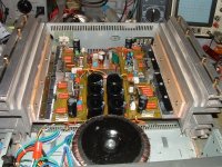
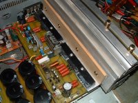
I completed the BJT quasi as per your design and layout.
And what a wonderful amplifier that one is, the dynamics are excellent
and the intrisic quality is admirable....Very satisfied with it!
I used three pairs of Sankens 2SC3857 on the outputs and the inputs are 2SC2240, matched pairs. The offset after adjustment is only 3 to
5 millivolts. My bias is 0.050 A but I'm not sure this will be the ideal
setting. May be you can make some correction on this one, could you?
I'm posting two images of the amplifier in a test bed that is not the definitive case, I still have to devise a cabinet for it with the whole
amplifier being so big and the transformer too. By the way the supply voltage is +- 62 volts.....
Again Quasi thanks for the excellent design.
I'm sorry if I'm hijackng the thread but I wanted to let you know that
I completed the BJT quasi as per your design and layout.
And what a wonderful amplifier that one is, the dynamics are excellent
and the intrisic quality is admirable....Very satisfied with it!
I used three pairs of Sankens 2SC3857 on the outputs and the inputs are 2SC2240, matched pairs. The offset after adjustment is only 3 to
5 millivolts. My bias is 0.050 A but I'm not sure this will be the ideal
setting. May be you can make some correction on this one, could you?
I'm posting two images of the amplifier in a test bed that is not the definitive case, I still have to devise a cabinet for it with the whole
amplifier being so big and the transformer too. By the way the supply voltage is +- 62 volts.....
Again Quasi thanks for the excellent design.
Attachments
Great work jmateus looks great, hope my looks that good
BTW i didn't even know that was a BJT version
BTW i didn't even know that was a BJT version
a1.0 The PSU is a transformer (either centre tapped or dual secondary), bridge rectifier and smoothing capacitors.Juan Spektor said:NMOS200 so i decide to build it.
q1. Are you using one psu in special or are they build at your own criteria.
q2. What is VA? you use it all the time, i only know watts (V*A) i look around and only found formulas beyond my understanding. some one help me here please.
q3. what transformer should i use for 2x50W 8ohm, like votls and amperes that should clear me something. (i think that a 25-0-25 center taped at 10 ampere should work and some 10,000 caps should work for the psu)
4. are noms350 and nmos500 also 4ohm like nmos200
a2.0 The transformer VA rating should be about 1.5times the total output power.
a3.0 50W+50W requires about 150VA. Into 8ohm loads you need 30-0-30Vac or possibly 28-0-28Vac.
Could you want 4ohm ability from this amplifier?
Then the output voltage will try to push 100W +100W into 4ohm and you now need 300VA for a 2channel amplifier.
You also need to double the smoothing capacitance for the half impedance loading.
I recommend +-20mF/channel for 8ohm loading and +-40mF/channel for 4ohm loading. That is a lot of 10mF capacitors.
Great work Jmateus
.
Hi Jmateus,
That looks like an excellent variation of the bi-polar version. Congratulations are in order, especially as I haven't even fired mine up yet.
Good to read that you are please with the sound. The bias at 50mA might be only a fraction low, you could add another 10mA or 20mA and see if there is much difference. Great work again
Cheers
Q
Juan Spektor said:Great work jmateus looks great, hope my looks that good
BTW i didn't even know that was a BJT version
Here's a link to the BJT version. The thread is called "Brother of Quasi". http://www.diyaudio.com/forums/showthread.php?s=&threadid=88258
Cheers
Q
Nope, I think it is all the same. The math I've been taught to use actually gives a very close result:AndrewT said:
Tom,
your US transformer must be different from our UK versions.
(40Vac x 1.414) - 1.4V= 55.16Vdc
The capacitor bank will load down the transformer a little and if you add a .1uF across the filter cap you load it down a little more. Real world measurment would be just under 55Vdc and in my testing it is always very close. Add on a bleeder resistor and the idle current demand of the circuit connected and it all drops further.
Cheers,
Shawn.
- Home
- Amplifiers
- Solid State
- Power amp under development