Cost Estimate
I wont have access to my friends milling machine for about a week so the case will be delayed.
I thought in the meantime I would post the real project cost to me in $ AUS. After all this is part of the essence of DIY (bang for buck & personal satisfaction).
There has been talk in this forum about how much things cost and what DIY'ers can and cannot afford so I hope many will be pleasantly surprised and encouraged to try what I have done here.
The total monetary cost for this amplifier (200 watts per channel 8 ohms) is just over $80.00 AUS ($60.00 US). This has been achieved by using second hand parts found in recyclers, scrap metal merchants, friendly electronic workshop bins and the roadside.
Of course I have not put a value on the time.
I have attached details of the costs (I hope I haven't missed anything)
Cheers
Attachments
Hi quasi,
I think it took a lot of time to document your work. Most of us don't do that (and maybe should). This is well worth it considering the alternative to a hobby is sitting on a couch drinking beer.
-Chris
I think it took a lot of time to document your work. Most of us don't do that (and maybe should). This is well worth it considering the alternative to a hobby is sitting on a couch drinking beer.
-Chris
Finished at last.
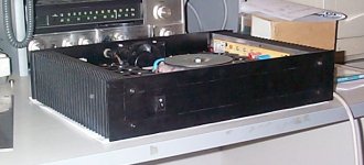
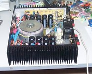
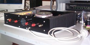
Well after taking a lot longer than I thought this amp is finished at last.
The amp delivers 210 watts into 8 ohms and 360 watts into 4 ohms before the onset of clipping.
Here are some piccies of it. The pencil marks on the front panel will be removed tonight.
Thanks to all who have helped and commented along the way.
I will post final layouts and schematics over the next week or so.
Cheers
Attachments

very-very-very nice work, my friend!
congratulations!!!
i've got a little question:
isn't the 500VA transformer undersized for a 2*360W amp?
the amplifier picks up 1000W power from the trafo when working fully to 4ohm. I think the trafo would be so hot in this case!
congratulations!!!
i've got a little question:
isn't the 500VA transformer undersized for a 2*360W amp?
the amplifier picks up 1000W power from the trafo when working fully to 4ohm. I think the trafo would be so hot in this case!
edl said:i've got a little question:
isn't the 500VA transformer undersized for a 2*360W amp?
the amplifier picks up 1000W power from the trafo when working fully to 4ohm. I think the trafo would be so hot in this case!
Hey Edl,
Of course you are right if the amp was asked to deliver 2 x 360 watts of sine wave for extended periods. This would cause the transformer to burn out. Music is nothing like sine wave fortunately and even at full output the transformer is probably only delivering an average of maybe 100 watts. I believe it's completely irrelevant testing an amp for continuous RMS power for more than say 15 seconds, because this is never required under any music condition.
The test I did was with one channel driven. With both channels driven the continous power output would be less. But again music is nothing like the test condition so the actual effective output is probably more than 360 watts. This could be called dynamic headroom I suppose.
Of course the above applies to a class A/B amplifier and not to a class A.
Cheers
hi Quasi!
very thank you for the answer.
now I see, why you applied only a 500VA rated trafo!
I don't even listen sinusoidal too!🙂
One more thanks for your very nice design!
Let"s enjoy your super amplifer!😉
very thank you for the answer.
now I see, why you applied only a 500VA rated trafo!
I don't even listen sinusoidal too!🙂
One more thanks for your very nice design!
Let"s enjoy your super amplifer!😉
Hi,
are you still taking on board suggestions?
I note you are thinking of altering the output cabling A/B etc.
How about running separate feeds to each set of speaker terminals from the ground and output source? A little less interaction if you decide to bi-wire a two way speaker.
While you have designed & built this project I am still thinking about topology etc.
WELL DONE.
AndrewT said:Hi,
are you still taking on board suggestions?
I note you are thinking of altering the output cabling A/B etc.
How about running separate feeds to each set of speaker terminals from the ground and output source? A little less interaction if you decide to bi-wire a two way speaker.
While you have designed & built this project I am still thinking about topology etc.
I hadn't thought about splitting the speaker gnd and amp wiring for the A/B switching but it is an interesting thought and it would be very easy to achieve. I can see how it could improve a split speaker feed although I would run a true bi-amp system under those circumstances.
I know what you mean about "thinking about topologies". Towards the latter part of this thread you will see that I drew the line and started building. It would quite easy to try and perfect everything before the soldering iron came out but eventually something has to be built. Having said that I have seen some designs in this forum that I like e.g. the Double Long Tail Pair by Lars and others. I want to design and build a subwoofer next so the DLTP will probably be used.
rajeev luthra said:GOOD JOB QUASI
Is the current sharing equal , did you match the outputfets ?
I did not match the FETS but I did measure the voltages across the 0.33 ohms emmitter resisitors at idle and they are all conducting. The amplifiers output power is quite modest and the heatsinks are large so everything will be ok. Matched FETS may offer better distortion but I am over 40 🙁 and would never hear it.
Thanks to both of you for your compliments and feedback.
Cheers
Excellent Work!
Hi quasi,
Excellent work on this amp, pcb design, case and layout. I have been following along patiently and quietly 😉
quasi or anyone,
A few questions if I may:
1) I happen to have some 44-0-44 960VA toroids at a really good price. Very heavy monsters as well 🙁( 🙁( I also have some 15-0-15 225VA, and 25-0-25 225VA toroids, and a 20-0-20VA 160VA toroid. Can you advise me what formula I need to use to determine power at X impediance? I have a spreadsheet with two sets of formulas to calculate this information but it seems the numbers those two formula sets create do not come close to 78V for 210W/360W 8/4 ohms. These formulas are similar but to various degress take into account losses that suggest about 270W/520W for 8/4 ohms, so I am at a "loss" (no pun intended) what formula to use to calculate for the toroids I have.
2) Do any values, not ratings need to be changed when using supplies based on toroids of 15-0-15, 20-0-20, 25-0-25 or 44-0-44? If so maybe the formula to do so would be better than providing the values of any change?
3) You had hinted you had some other ideas, but decided to put a stake in ground and build. Beyond your interest in the use of Double Long Tail Pair for next round any other ideas in general sense you had on list that you did not do in current design?
4) Based on your 210/360 8/4 ohm test results would it be fail to assume 100/200/400 for 8/4/2 as you have built, music rating not sine wave input?
5) If matching of output devices was done could one reduce the emitter resistors to 0r33 or even 0r22? My preference would likely be to 0r33.
6) I assume the emitter resistors are 5W, and all otehr resistors are 0.25W?
7) Would I be correct to assume R16/R17 determine the gain, which is 33k0/1k0=33? Any thoughts to change to 27k0/1k0=27?
Regards,
John L. Males
Willowdale, Ontario
Canada
18 March 2005 08:02
Keypunch's questions;
Hey John, hope the following helps.
Your 44 - 0 - 44 900VA transformer with this module would make a great medium power amplifier using this module.
The way I determine an amps power output is like this;
First I determine the available DC rails at full power i.e. AC volts (one winding) - rectifier drop(v) - transformer's regulation * 1.414. I generally use 1 volt as the full rectifier drop although this can often be higher.
So if your 900va transformer had regulation from idle to full power of 5% then your available full power rails would be 44v - 1 - 2.15v * 1.414 = 57.7 volts.
Then I work out RMS voltage available to the speaker i.e. DC volts (one rail) - output transistor drop(v) * 0.707. For your large transformer this is 57.7v - 7 * 0.707 = 35.84 vRMS.
Using ohms law I work out the power i.e. 35.84^2 / 8 ohms = 160 watts. YOu can use the same formula to work out power into 4 and 2 ohms but make allowances for the additional voltage drop in your power supply and output FETS. Power into 4 ohms would be around 290 watts.
Unfortunately without knowing the exact details of regulation and losses in the rectifier, capacitors, wiring and output transistors power calculations are only estimates. It dB terms it does not make much diferrence though.
2. For lower voltage rails the main change that has to be made to my circuit is resistor R7 in the first stage. This shares the negative rail voltage with T2 and must leave sufficient voltage for T2 to work properly. The constant current source is setup to provide about 2.7 mA and this causes a voltage drop across R7 of 45 volts. With full power rails of 57 volts approximately 12 volts is left across T2 so everything is ok. I would make sure that T2 always had at least 5 volts across it to allow for power fluctuations. For rails lower than 50v I would change R7 to 10k.
It would not make sense to use this design for DC rails of less than say 45 volts ( AC 31 - 0 - 31) because the modest power output could be delivered by simpler designs.
3. Yes other ideas for the module were, the DLTP (double long tail pair), a split positive rail to drive the positive output FETs harder, gate protection for the output FETS and cascodes for the first and second stage.
The split positive rail topology circuit I have already posted in "Another quasi-complimentary design". This amp should in theory provide slightly more power for the same DC rails. It also has a cascoded second stage in the high power version and gate protection zeners.
I am about to start on a clipping indicator that will look like a 4 step VU meter but will actually show power output in terms of 25%, 50%, 75% and 100% (clipping) referenced to the instantaneous rail voltages.
4. Music power is a matter of opinion. For many it's the peak available voltage^2 / load. So for 44-0-44 AC the this gives you music power of 300/600/1200 watts.
5. Yes the better matched your output devices are the lower you can make your source (emitter) resistors. But even closely matched FETS do not share current. The one that starts to conduct more, warms up more and conducts more and warms up more etc. I prefer to run 0.47 ohms but feedback (peer pressure?) directed me to reduce the value to 0.33. Resistors of 0.1 are too low to do any good.
6. Yes
7. Yes. Indeed less gain makes more sense with lower rails. Less gain usually also means more linearity.
Whew !!!!.....cheers
Hello Quasi ,
You said your next project will be the protections etc for this amp , how will you sence current ? also please post all that on this thread only .
Regards,
Rajeev
You said your next project will be the protections etc for this amp , how will you sence current ? also please post all that on this thread only .
Regards,
Rajeev
- Home
- Amplifiers
- Solid State
- Power amp under development