The quasi topology will clip the -ve waveform earlier than it will clip the +ve waveform.
Since you will not knowingly listen to music and audio with deliberately clipped output signals, this earlier clipping is not an issue.
Sort the problems and listen to unclipped music.
You did not answer the questions:
Since you will not knowingly listen to music and audio with deliberately clipped output signals, this earlier clipping is not an issue.
Sort the problems and listen to unclipped music.
You did not answer the questions:
negative oscillation.
Is that due to clipping?
What load and what voltage?
What is the voltage at the output when the 8r0 dummy load is connected?
Last edited:

The amp can not work well because you need about + 10 V / bootstrap to drive negative rail for full rail swing / perefct sine wave without oscillation. Thats why quasi make Acrtk Nmos Amp. This amp have + 10 V to fix this problem, check the schematic you will see
Class D work same, using 2 N Channel Mosfets and have +12 V Bias / Bootstrap for drive negative Mosfets
I don think so... parasitic oscillation it's not in ralation with +10V bootstrap...... with the 39nF on the gate sinewave is perfect.....!
mrlord... it appears you are posting under two separate identities, something expressly forbidden by the forum RULES
Please let us know which name you wish to be know by and the accounts can be merged.
I'm very sorry for my mistake. You can merge on this account.
Offset voltage? About 5mV....What is the voltage at the output when the 8r0 dummy load is connected?
The quasi topology will clip the -ve waveform earlier than it will clip the +ve waveform.
Since you will not knowingly listen to music and audio with deliberately clipped output signals, this earlier clipping is not an issue.
Sort the problems and listen to unclipped music.
You did not answer the questions:
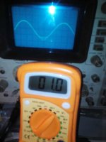
I don't tink this is a problem of clipping, you can watch the photo. Parasitic Oscillation i'ts another problem, I believe.....
I will soon post other photo with te cap connected.
I'm very sorry for my mistake. You can merge on this account.
OK, so its mrlord25 into mrlord.
Might take a little while to show.
output offset is measured when the output has no load.Offset voltage? About 5mV....
The scope shows a sinewave with oscillation when an 8r0 dummy load is connected.
What is the voltage across the load.
Either Vac, or Vpk, or Vpp?
Not much, in this moment I can't measure.... about some volt, but I remember 170 mA.output offset is measured when the output has no load.
The scope shows a sinewave with oscillation when an 8r0 dummy load is connected.
What is the voltage across the load.
Either Vac, or Vpk, or Vpp?
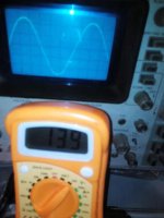
@ 13.9Vac output there is no oscillation !
@ 1Vac output there is the interference again !
13.9Vac = full power. That's 24W into 8r0.
@ 1Vac output there is the interference again !
13.9Vac = full power. That's 24W into 8r0.
In fact, seems a little bit poor... I not understand the reason.@ 13.9Vac output there is no oscillation !
@ 1Vac output there is the interference again !
13.9Vac = full power. That's 24W into 8r0.
But @13.9 the absorbtion is 0.8A for the positive rail: (0.8 + 0.8 ) x 130V =208 W. It's correct?
No.
That's not the way ClassAB works.
Measure the Vdrop of the emitter/source resistors and use those measurements to determine the currents. You will need a scope and an isolating transformer to let the scope ground link pull the resistor voltage to the scope voltage.
That's not the way ClassAB works.
Measure the Vdrop of the emitter/source resistors and use those measurements to determine the currents. You will need a scope and an isolating transformer to let the scope ground link pull the resistor voltage to the scope voltage.
your design is different without any protections...check my PCB
please provide your schematic
sir, can u send me the circuit diagram of NOMS 2709201 ...input rail +-50v...low power mosfet amps..
What the ,,,,?NOMS 2709201
I did a search and the ONLY location for the search string is your post.
can any one send me the original source nd circuit diagram of of this amplifier....http://www.diyaudio.com/forums/atta...nt-nmos-class-ab-2709201-small-power.pdf....:)
noms small
Sir Andrew T .Sir NMOS had posted the project ..nmos small ab amplifier useing irfp460..in +-50 v rail..http://www.diyaudio.com/forums/solid-state/43331-power-amp-under-development-376.html#post2727400
What the ,,,,?
I did a search and the ONLY location for the search string is your post.
Sir Andrew T .Sir NMOS had posted the project ..nmos small ab amplifier useing irfp460..in +-50 v rail..http://www.diyaudio.com/forums/solid-state/43331-power-amp-under-development-376.html#post2727400
Last edited:
- Home
- Amplifiers
- Solid State
- Power amp under development