I decided to upgrade my poweramp measurement system.
The devices:
1/ ultra low distortion sine wave oscillator - I bought Victor's 1k and 10k
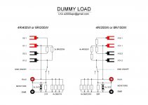
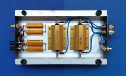
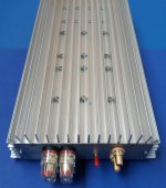
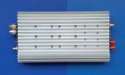
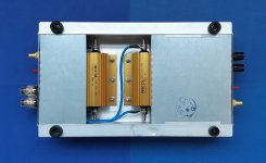
2/ dummy load - designed and made by me
3/ passive voltage divider - under development
4/ passive notch filter- schematic Victor, made by me
5/ post notch buffer - under development - powered by two 9V battery
6/ PC sound cards I have
- ESI Juli@ PCI
- Asus Xonar STX II
- X-Fi USB HD modded Improving A/D perfromance of Sound Balster X-fi Music (SB1240) - and a Puzzle!!! - diyAudio

the dummy load
The devices:
1/ ultra low distortion sine wave oscillator - I bought Victor's 1k and 10k
2/ dummy load - designed and made by me
3/ passive voltage divider - under development
4/ passive notch filter- schematic Victor, made by me
5/ post notch buffer - under development - powered by two 9V battery
6/ PC sound cards I have
- ESI Juli@ PCI
- Asus Xonar STX II
- X-Fi USB HD modded Improving A/D perfromance of Sound Balster X-fi Music (SB1240) - and a Puzzle!!! - diyAudio
the dummy load
Attachments
the notch filter


the voltage divider schematic

voltage divider pcb is ready for fabrication
balanced system will come after SE done, maybe 🙂


the voltage divider schematic
You need voltage dividers and balanced input, if you are serious.
voltage divider pcb is ready for fabrication
balanced system will come after SE done, maybe 🙂
I concur with PMA, balanced inputs are very useful for avoiding ground loops amp input-output (and measuring digital amps), esp. when Juli@ offers reasonable balanced inputs with quite high input voltage for 0dBFS (20Vpp hot-cold)
Ground loops aren't a big problem in my system. The voltage divider has a GND switch. For floating oscillators grounds are connected. If you use the sound card's output, the ground has to be disconnected at the poweramp side. (or coupled via 1k resistor )
very nice work!😉I decided to upgrade my poweramp measurement system.
Have you done a loopback with the monitor on the load, as the zener protection may cause a roll-off circa 50-200kHz and may be quite signal voltage variable?
Are you grounding the load chassis in any way, or just leaving it as isolated metalwork?
Are you grounding the load chassis in any way, or just leaving it as isolated metalwork?
Zeners are optional because the divider has fixed value. In the past I burned two sound cards, so I put zeners everywhere. The roll-off is much higher, above 1MHz, the divider output impedance is below 100R.
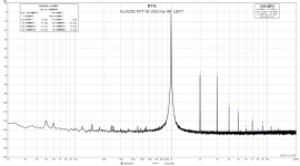
The heatsink is not grounded, here is a meauserement of my non-gnfb amp, mains related frequencies are below -120dB.
I'm planning to use switchable (ON/OFF) RC compensation network. First I need to measure the HS200 inductance.
TYVM
The heatsink is not grounded, here is a meauserement of my non-gnfb amp, mains related frequencies are below -120dB.
Those HS200 are not non-inductive. It may not matter if it's low enough, I'm just picky.
I'm planning to use switchable (ON/OFF) RC compensation network. First I need to measure the HS200 inductance.
very nice work!😉
TYVM
Attachments
Low voltage zeners may have substantial capacitance - it could be worth checking a loopback response to see if it comes in to the soundcard range and hence need a calibration file.
you are right
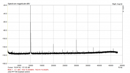
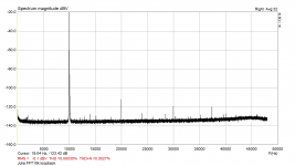
test1 : generator = victor's 10k (output imp 600R)
picture 1 : no zeners
picture 2 : two bzx83C3V3 zeners at the sound card input (input imp 5k6)
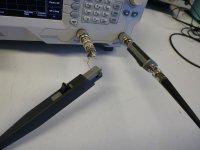
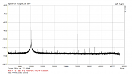
test2 : loopback (output imp 100R)
picture 3 : no zeners
picture 4 : two bzx83C3V3 zeners at the sound card input (input imp 5k6)
test1 : generator = victor's 10k (output imp 600R)
picture 1 : no zeners
picture 2 : two bzx83C3V3 zeners at the sound card input (input imp 5k6)
test2 : loopback (output imp 100R)
picture 3 : no zeners
picture 4 : two bzx83C3V3 zeners at the sound card input (input imp 5k6)
Attachments

Actually I was thinking more of a frequency response sweep response, and out to 96kHz, as possibly showing up some filter response.
That looks more like an influence due to the changing capacitance of the zener string as 1kHz signal voltage goes through a cycle.
That looks more like an influence due to the changing capacitance of the zener string as 1kHz signal voltage goes through a cycle.
For the clamping you would be better off with biased diodes. Use some 1n4148 reverse biased (batteries might work even) to limit the peak voltage. Very little current and not much cap modulation since the bias voltage will be larger than the signal.
In any case a significant overload with fry the diodes since you don't have current limiting in either case. You could use some small fuses. . .
In any case a significant overload with fry the diodes since you don't have current limiting in either case. You could use some small fuses. . .
I tried to find a diode with the lowest reverse current, ended up with dual BAV199 with max. reverse voltage 85V for 10 cents (for LKA - available in Czechia by GME). Two 12V A23 batteries last over a year (ideal for balanced inputs of Juli@ with max. voltage each lane at 10V), a check-up voltmeter costs 1 dollar from ebay. Of course a serial resistor limiting the current is important.
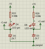
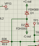
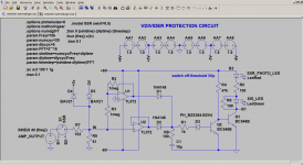
I have had excellent results with the attached. Set up a threshold voltage with biased zeners, in this example 4.7V. Then use ultra-low leakage diodes like the FDH300 as diode clamps. No influence down to -130dB. (The LEDs are just for power indication and can be deleted of course.
Jan
Jan
Attachments
Last edited:
I've done the diode clamp setup to save my precious $1 USB soundcards - haven't lost $1 yet - but the lack of a bias supply does mean something like a 9V battery.
There is at least a bit of series resistance in the jig.
There is at least a bit of series resistance in the jig.
Last edited:
Will not SSR in the signal path introduce some harmonic distortion due to some nonlinearity? I do not know, just asking. In low distortions everything matters 🙂
- Home
- Design & Build
- Equipment & Tools
- Power amp measurement system