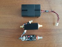
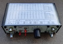
I made a compact version of the post-notch preamp. Same box (enclosure) as for notch, powered by external batteries. Gain is selectable by jumper, 1x or 100x. The PCB has two versions, one for single op-amp (OPA627,827,828, etc) and another for dual op-amp (OPA1656,etc). On the picture you can see boxed OPA827 with bypassed input/output caps (4mV output dc @40dB) and unboxed OPA2141 version (waiting for OPA1656). Second picture captures OPA827 output noise (amplification 100x) , input impedance is 50R.
Attachments

Last edited:
Jan, TY.
There's one thing I regret, I should have used BNC connector, it's far more better than RCA.
There's one thing I regret, I should have used BNC connector, it's far more better than RCA.
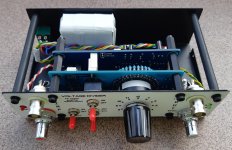
Almost finished voltage divider, AAA battery holders are on the way, till arrive I made a battery pack (white color on the picture).
The front board holds the divider/attenuator, mosfet SSR, mosfet driver while the rear one is a protection logic/driver.
The front board holds the divider/attenuator, mosfet SSR, mosfet driver while the rear one is a protection logic/driver.
Attachments

Jan, TY.
There's one thing I regret, I should have used BNC connector, it's far more better than RCA.
Yes my passive twin-tee is with BNC ;-)
Jan
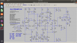
I'm playing with this LPF.
http://sim.okawa-denshi.jp/en/OPtazyuLowkeisan.htm


C1 is Wima MKS2, I don't have anything better at home
C2 is TDK MLCC C0G


http://sim.okawa-denshi.jp/en/OPtazyuLowkeisan.htm
C1 is Wima MKS2, I don't have anything better at home
C2 is TDK MLCC C0G
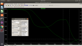
The test ( 1uF was replaced by two 2u2 in series)
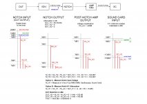
I use manual fundamental in REW. The graphs do not take into account the behavior of the passive filter on H2,H3 ...
1/ LPF is not used
D10s -3dBFS (1.42Vrms) -> Passive notch filter -> Post notch AMP +40dB -> Cosmos ADC unbalanced 1.7V range

After the passive filter correction we get
H2 = -158 + 9 = -149 dBc
H3 = -139 + 6 = -133 dBc
2/ LPF is used, powered by two 9V batteries
D10s -3dBFS (1.42Vrms) -> LPF -> Passive notch filter -> Post notch AMP +40dB -> Cosmos ADC unbalanced 1.7V range

After the passive filter correction we get
H2 = -162 + 9 = -153 dBc
H3 = -153 + 6 = -147 dBc
Nice !
probably a better quality C1 would give a lower H3
I use manual fundamental in REW. The graphs do not take into account the behavior of the passive filter on H2,H3 ...
1/ LPF is not used
D10s -3dBFS (1.42Vrms) -> Passive notch filter -> Post notch AMP +40dB -> Cosmos ADC unbalanced 1.7V range
After the passive filter correction we get
H2 = -158 + 9 = -149 dBc
H3 = -139 + 6 = -133 dBc
2/ LPF is used, powered by two 9V batteries
D10s -3dBFS (1.42Vrms) -> LPF -> Passive notch filter -> Post notch AMP +40dB -> Cosmos ADC unbalanced 1.7V range
After the passive filter correction we get
H2 = -162 + 9 = -153 dBc
H3 = -153 + 6 = -147 dBc
Nice !
probably a better quality C1 would give a lower H3
Last edited:
- Home
- Design & Build
- Equipment & Tools
- Power amp measurement system