If those are accurate, appears that the transistor (MPSA92) is defective. The voltage between the emitter and the base is too great. IT shouldn't be more than about 0.7v. Even if it's defective, the transistor is supplying voltage normally so that's not stopping the amp from oscillating.
Also, do you still have only 35v on the switched/control terminal before is switches to ground?
i changed mpsa92 now the voltages are good on the pins. and still have the same problem. also control terminal only reaches to 35v max then goes to ground suddenly when green light comes on.
Post the new voltages on that transistor.
What is the DC Voltage measured directly across R175 after switching to green?
What is the DC Voltage measured directly across the resistor connected to the collector of Q113 after switching to green?
73.8 73.3 73.8
R175 DC voltage is 7.7v
The resistor connected to collector is R179 and is having 0v
DC voltage on all terminals of Q112? Also voltage measured directly across both R172 and R173.
-7.4v -6.7v -0.4v
R172 0v
R173 0.3v
Something is wrong. If the voltage across R175 is only 7.7v and one terminal of that resistor is tied to the negative rail (if this amp is like similar amps), the emitter of Q112 could not be at -7.4v.
See if there is a broken trace or connection between R175 and the negative rail. If not, what is the end of R175 connected to other than the emitter of Q112?
See if there is a broken trace or connection between R175 and the negative rail. If not, what is the end of R175 connected to other than the emitter of Q112?
Something is wrong. If the voltage across R175 is only 7.7v and one terminal of that resistor is tied to the negative rail (if this amp is like similar amps), the emitter of Q112 could not be at -7.4v.
See if there is a broken trace or connection between R175 and the negative rail. If not, what is the end of R175 connected to other than the emitter of Q112?
One side R175 is connected -15v of 4580D and have -15.1v. The other side of resistor R175 is connected to emitter of Q112. And the emitter is not connected to anything else.
OK. That's different.
Are you 100% sure that Q110, 111, 114 and 116 are all good? Did you pull them and check them for leakage or open junctions?
I removed all transistors and tested them out of circuit and they are good
Did you test for open junctions?
Voltage on all terminals of Q110 and 111?
I just took all transistors out and cleaned the board then put back all transistors. Now luckily I am getting oscillations but going into protect. And it cycling trying to come on then going protect.
The inductors on these tend to short where the inner terminal windings go over the top of the other windings. That could be the reason for the high current draw.
When it trying to come on there is dc on speaker terminals.
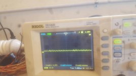
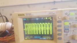
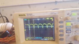
What sort of oscillations are you seeing on the output transistors (from post #51)?
i am attaching the oscillation pictures. i am getting only on high side low side cant see much of any change.
Attachments
You need to get good drive signals for the outputs before installing them.
When you post scope waveforms, label them as to precisely what point your were probing.
So remove all the outputs? All those waveforms are of high side fet gate. Waveform is not constantly staying only comes when it tries to come on so I took speed clicks with my camera so I got those waveforms.
In most any amp that's not cooperating (or would be a pain to remove all of the installed FETs), you try to get the drive waveforms before installing this FETs. This applies to the PS and the output stage.
It may not always be possible to troubleshoot without the FETs but it generally simplifies the repair process.
It may not always be possible to troubleshoot without the FETs but it generally simplifies the repair process.
In most any amp that's not cooperating (or would be a pain to remove all of the installed FETs), you try to get the drive waveforms before installing this FETs. This applies to the PS and the output stage.
It may not always be possible to troubleshoot without the FETs but it generally simplifies the repair process.
I removed all the outputs. no drive signal at all. amp coming on.
- Status
- This old topic is closed. If you want to reopen this topic, contact a moderator using the "Report Post" button.
- Home
- General Interest
- Car Audio
- Power Acoustik BAMF 5500 driver board part number