For this amp the contacts are good. i also tried by twisting but no luck. i took the driver board again and washed it clean and with microscope checked if everything is good then i put the driver board back i am now getting the amp to come on. but there are no oscillations. i wonder if it is going into mute.
What's the circuit board designation for it?
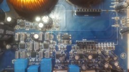
It have no name on the board any where.
circuit board designation = ICxyz, Rxyz or Qxyz.
Optocoupler is IC108
Outputs Q135 to 139 and Q130 to Q134
Driver board connector CN102 CN101
Main rectifier D324 and D323
Photo of the area with the opto-coupler?
Attachments
Which pin of the driver board is connected to pin 3 of the opto?
2nd pin of CN101
Does that pin have near rail voltage just after powering up and then drop to near ground after a few seconds (when the LEDs switch from red to green and up to 15 seconds in some amps)?
voltage increases upto 36v then goes to ground as the green led comes on.
it have very fine almost like sinewave on high output gate
Do you see an input signal of the frequency that you're driving into the amp on any pin of the driver board?
What's the rail voltage in this amp?
That signal should be at least at rail voltage (maybe rail +15v) before switching. The switching to ground is used to enable the class D circuit.
What's the rail voltage in this amp?
That signal should be at least at rail voltage (maybe rail +15v) before switching. The switching to ground is used to enable the class D circuit.
Do you see an input signal of the frequency that you're driving into the amp on any pin of the driver board?
What's the rail voltage in this amp?
That signal should be at least at rail voltage (maybe rail +15v) before switching. The switching to ground is used to enable the class D circuit.
yes i see clear input signal on 7pin of CN101.
voltages on Rectifier is +56v and -56v.
No the signal i told is lesser than 1v i dont think it is a proper signal.
"That signal should be at least at rail voltage (maybe rail +15v) before switching. The switching to ground is used to enable the class D circuit."
^^^ Could have been better written.
The voltage on the switching/control pin of the control board (and pin 3 of the opto-coupler) should be at least at rail voltage (maybe rail +15v) before switching. The switching to ground is used to enable the class D circuit.
Look at the diagram (posted previously in link to another DIY page) and see if it's the same basic circuit as in your amp.
http://rollmeover.com/bronco_fab/amps/asian_clone_driver/gac_driver.pdf
"That signal should be at least at rail voltage (maybe rail +15v) before switching. The switching to ground is used to enable the class D circuit."
^^^ Could have been better written.
The voltage on the switching/control pin of the control board (and pin 3 of the opto-coupler) should be at least at rail voltage (maybe rail +15v) before switching. The switching to ground is used to enable the class D circuit.
Look at the diagram (posted previously in link to another DIY page) and see if it's the same basic circuit as in your amp.
http://rollmeover.com/bronco_fab/amps/asian_clone_driver/gac_driver.pdf
What happens if 4580 if goes bad on driver board will it make oscillations? I did not check that.
It would probably depend on how it failed.
Did you look to see why the voltage on the switching terminal wasn't going higher?
What is the voltage on the emitter of Q113 (or whatever the equivalent is on your board)?
i have 73v on emitter black probe on power supply input ground terminal.
What's the voltage on all 3 terminals of that transistor after the LED switches to green?
76v 73v and 76v
If those are accurate, appears that the transistor (MPSA92) is defective. The voltage between the emitter and the base is too great. IT shouldn't be more than about 0.7v. Even if it's defective, the transistor is supplying voltage normally so that's not stopping the amp from oscillating.
Also, do you still have only 35v on the switched/control terminal before is switches to ground?
Also, do you still have only 35v on the switched/control terminal before is switches to ground?
- Status
- This old topic is closed. If you want to reopen this topic, contact a moderator using the "Report Post" button.
- Home
- General Interest
- Car Audio
- Power Acoustik BAMF 5500 driver board part number