Hello all.. I'm having a problem with an amp that my brother has had for quite a few years... he only used it for about a year and never abused it. Then one day it just stopped working.. All it does is moves sub back and forth at a slow rate even when not hooked to rca jacks. When it does this it draws a lot of power from the power source and the red led light on the board stays lite the whole time and blinks with the draw of power. All wiring is hooked up right. I was wondering if someone had this problem before and how it fix it. Its a Power Acoustik Fire & Ice FI2X-1600 amp.
If it draws excessive current with only B+, ground and remote connected, it probably has shorted output transistors.
If this is one of the amps that has two blue boxes inside the amp and the large one says 'high voltage', be careful handling the small blue box. It's the one with high voltage.
If this is one of the amps that has two blue boxes inside the amp and the large one says 'high voltage', be careful handling the small blue box. It's the one with high voltage.
Yes this does have a box that says high voltage on it. it plugs into the other part of the circuit board from the left hand side. Is there anyway that I can test the transistors or anywhere I can buy them from like a radio shack or something?
Let it sit for a while unhooked, then take a meter at voltage and check around for power on the rails and transistors before you work in it.
Generally you take the clamp(s) off to get the part number on them, and test between the legs to see if they are shorted with an ohm meter on ohms test. It may have two different types of transistors on outputs; look at board and see what ones are powered via common source they should be the same, ie: find ones that typically will have middle or right legs connected in parallel. Usually there is two groups per channel, and they may or may not be the same part. If any one is shorted between legs it is bad and may short the rest in parallel.
Get the part number and then figure out where to get them. I have not seen one of these but Perry likely has.
Perry Babin said:If it draws excessive current with only B+, ground and remote connected, it probably has shorted output transistors.
If this is one of the amps that has two blue boxes inside the amp and the large one says 'high voltage', be careful handling the small blue box. It's the one with high voltage.
Isn't that box just to run the indiglo or bling bling neon in the amp? Can it just be unplugged on the low voltage input side of the box? Just wondering, I remember pulling a few of them apart a few years back and they had that box.
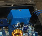
I already unplgged that box the the neon and the neon itself when i pulled the cover off.. I don't want to seem like an idiot but the trans your talking about is the yellow round thing at the bottom of the attached pic from perry? I'm no electronics expert by far but I know basic 12v circuits pretty well and obviously know how to check resistance in circuits. 😎
The yellow component in the photo is an inductor. The transformer will be larger and the core will be parallel to the board instead of perpendicular to the board.
What have you checked so far?
Have you found any defective components?
If you're unfamiliar with the terminology and the various components, take a quick look at the basic repair page (link in sig file below).
What have you checked so far?
Have you found any defective components?
If you're unfamiliar with the terminology and the various components, take a quick look at the basic repair page (link in sig file below).
I've looked over your link and understand somewhat what most the parts do... I had to use a headlight to keep from blowing the fuses. I checked voltage between the outside prongs on the transistors for the power side i believe.. I got 1.95 volts when the input voltage to the amp was around 6 volts because of the headlight resisting... I also just the resistence in the same ones and didn't find any that seemed to be shorted. Is there a order of things to check to find the problem or is it just a guessing thing with it?
I also checked the transistors or whatever they are on the other end of the amp and noticed on 2 of them that they seemed to be connected on the outer 2 prongs.???? Just let me know with any help you can... thanks
I also checked the transistors or whatever they are on the other end of the amp and noticed on 2 of them that they seemed to be connected on the outer 2 prongs.???? Just let me know with any help you can... thanks
The ones that appeared to be shorted on the outer legs are probably the rectifiers.
With the headlight in the circuit and the amp powered up, measure the voltage across ALL of the large emitter resistors. They all should have approximately 0.000v across them. Do any have more than 0.000v?
With the headlight in the circuit and the amp powered up, measure the voltage across ALL of the large emitter resistors. They all should have approximately 0.000v across them. Do any have more than 0.000v?
How can i post a pic of the amp on here so you can show me what to check.. I don't want to check the wrong thing thinking that its what your talking about? I tried attaching one but it didn't work
I'm thinkin they are the bigger light blue resistors right? If so i'll check them and let ya know.. They shouldn't have any voltage at all right? And i just put the positive on one side and the other lead on the ground???
Large light blue resistors are probably the emitter resistors. There will be one for each output transistor.
When you measure the voltage across the emitter resistors, you will place one lead on each side of the resistor. There should be no voltage across them. If you find one or more with voltage, it will help to find the defective transistors.
If you attached the image and then previewed the message, the attachment would have been lost (this problem should be solved in the next few months). Don't use the preview. Copy the message before trying to post it with an attachment. If the image is too large, the message may be lost.
If you can't post the photo, email it to me at the highest resolution possible. If you send more than one, zip them and send one file.
babin_perry@yahoo.com
I measured across the blue resistors that are close to the transformers and got no voltage. I checked the voltage across 2 green ones on the audio side of the amp and got 12v at them when the input amp voltage is around 6. Not sure what it means but thats the latest that i have found.
I emailed you perry with the zip file with the pics
I emailed you perry with the zip file with the pics
I'd recommend that you clamp the transistors to the heatsink when testing. It takes only a few seconds for them to overheat and fail when they're not tightly clamped to the heatsink.
This amp uses ceramic emitter resistors. It won't be possible to measure across them directly when the amp is in the sink. Place the red lead on the E terminal of Q114 and the black lead on the E terminal of Q115 and power up the amp.
Do the same for Q214 and 215.
Remember, the voltage will be very low (well under 1v).
Heatsinks were off just for the pics...
Q114 and Q115 E's had no voltage
Q214 and Q215 E's had .09-.10 volts
Q114 and Q115 E's had no voltage
Q214 and Q215 E's had .09-.10 volts
That tells you the problem is on the side with Q214/215.
Pull the output transistors on that side and recheck them out of the board. Check with the meter set to diode-check and with it set to resistance. You shouldn't have any readings less than 0.4 on diode check or less than 2M ohms on resistance. You're likely to find 1 or two that are defective.
If none of the output transistors are defective, you may have a defective driver transistor or a broken solder connection in the bias circuit.
If they're defective, you'll typically find a direct short (~0 ohms) between two or more of the leads.
Does your multimeter have diode-check?
Does your multimeter have diode-check?
- Status
- Not open for further replies.
- Home
- General Interest
- Car Audio
- Power Acoustik Amp