By the way, I found an earlier post suggesting that R71 & R72 be connected to ground if the GNFB is lifted. I did not do that, I didn't understand why you would. Any help??
Not sure why you would need to, as the grids are referenced to ground thru R68 & R70, whether the GNFB is connected or not. At least that's how it looks to me on the schem.
jeff
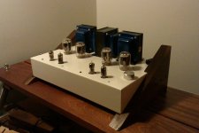
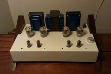
I finished my DCPP build a few weeks ago, and I've been enjoying the sounds coming from this amp! (Pictures below)
I've noticed a few things out-of-spec, though, and just wanted to see if anyone had any advice on how to get these numbers more in-line with what I'm seeing on the schematic.
First off, it's my first build so I've built it using 6JN6s, but everything else is pretty much straight from Pete's BOM, so nothing exotic is in play here. Iron is the standard Edcor set.
I balanced LB1/2 and RB1/2 to show 400mV. I don't have any distortion measuring equipment, so I've largely set DBAL by ear. B+ is 325V, and the screen voltage (measured at R42) is 150V.
With all of this set I'm seeing about 130V on TP11 & TP9, BUT about 185V on TP12 & 10. The schematic shows that this is supposed to be about 130V.
As well, the power transformer seems to be running a bit hot. I've had it on for a couple hours now and I can put my hand on it for about 2-3 seconds before it becomes uncomfortable.
So basically everything seems to be working well, except for a moderately high voltage on TP10 & 12 and a warm PT.
Any clues? Thanks.
Attachments
Turn-off thump
Does anyone have a suggestion on how to get rid of the turn-off thump caused by the DC voltage on the grid of the second tube? Pete mentions this in his article and says it can be eliminated with a much larger value of gridstopper. I believe he mentioned 47K. I would like to avoid using a gridstopper that high.
In my case, there is a 0.4 volt pulse on turn-off, which causes my speaker cones to move out quite a bit. I haven't had any problems but I know that can't be a good thing. Since moving to high-efficiency speakers, I have taken to disconnecting one speaker lead each time I turn off the amps. I am considering a switch on the outputs that would do the same thing, but of course I hate to put an unnecessary switch in the output. Ideas?
My speakers are 91dB (B&W 604s) and I don't experience the 'thump.' How sensitive are your speakers?
My speakers are 98db. With my 90db speakers, there is the same noise but the woofers can take a lot of power and I am not as concerned about damaging them.
Hello everyone:
Newbie here. I know which way to hold the soldering iron, and I have a scientific background, so I know enough to be very very dangerous...
I am waiting for transformers to finish my first amp (Tubelab spp) and assuming that one is successful, I was looking for my next project and found Mr. Pillet's PP amp. I tried to read the entire thread but at my age what remains is debatable. The power amp from the original design is an Edcor XPWR139. I saw that Edcor offers the XPWR205, which, for few more $, has 300-50-0-50-300 taps with the same amp rating (200 mA). Can this be used to obtain a bit more output power without major modifications? Also, if one changes output tubes to get more power, what would be a more suitable OPT for say 40-50 watts out? Besides the power requirement, one has to look at the output impedance of the output tubes and match it, correct?
Thanks for all and any info you may provide. And remember, I am a newbie 🙂.
Marco
This amp is loud at 17-20w. If you're worried about it not having enough volume, I can put your mind to rest. With mine I rarely have it up over half, and I haven't yet been able to drive it to clipping. (using an ODAC for input).
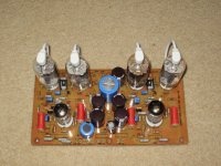
I've been building my own designs based on PCB design and fabrication. If you want 50-60 watts/channel, ensure power supply, 60 watt output iron, use the larger plate sweep tubes e.g. 6lb6 ...........
I prefer the 6.6kraa for lower distortion without feedback. 4.3k raa can be used with feedback.
My 40watt/channel sweep tube amps are more than adequate for the 89db efficient 4 ohm speakers in the listening room.
I prefer the 6.6kraa for lower distortion without feedback. 4.3k raa can be used with feedback.
My 40watt/channel sweep tube amps are more than adequate for the 89db efficient 4 ohm speakers in the listening room.
Attachments
Last edited:
When going to higher power output, make sure the power xfmr CURRENT rating increases accordingly to allow for the increased power. Especially if the OT primary Z is lowered for some bigger tubes, since the tubes will draw more current then, even for the same power.
Hello everyone.
Thank you for the point about current...
I really don't want anything enormous, just a bit more than the 18W of the unmodified design (I am finishing Tubelab SPP amp and that is spec-ed for 18W so next one has to be bigger, right 😀 ?)
Yes, I have read all the thread but there is a lot of info
 to digest and need some guidance...
What power transformer to use if I want to push it a bit? I have seen the specs for the Antek AN-4TK360. This can be used to provide 360-0-360 vac, and 5 A of 6.3 V for the filament. After rectification, this should give 430 to 450 of B+ .
By adding a small Antek AN-0240 I could then create the voltage necessary for the C- supply (-60 V). Is that correct? Any Board changes?
Suitable OPT need to be decided, as I have none on hand. Edcor seems to have many that will do.
I have, on order, lowly 6JM6 (the ones with the cap).
How low could I push the Input impedance of the OPT to get more power out with these tubes? Can they withstand what I plan to feed them, or should I just order something beefier?I am not a tube person so all these 4-letter alphanumeric codes make my head spin 🙂.
Many question but I want to be sure before I turn the switch on.
As Tubelab said, I am a bit contrary to release the "magic smoke" from my components, They don't work anymore after that😀.
Thanks for any and all info.
Marco
Thank you for the point about current...
I really don't want anything enormous, just a bit more than the 18W of the unmodified design (I am finishing Tubelab SPP amp and that is spec-ed for 18W so next one has to be bigger, right 😀 ?)
Yes, I have read all the thread but there is a lot of info
What power transformer to use if I want to push it a bit? I have seen the specs for the Antek AN-4TK360. This can be used to provide 360-0-360 vac, and 5 A of 6.3 V for the filament. After rectification, this should give 430 to 450 of B+ .
By adding a small Antek AN-0240 I could then create the voltage necessary for the C- supply (-60 V). Is that correct? Any Board changes?
Suitable OPT need to be decided, as I have none on hand. Edcor seems to have many that will do.
I have, on order, lowly 6JM6 (the ones with the cap).
How low could I push the Input impedance of the OPT to get more power out with these tubes? Can they withstand what I plan to feed them, or should I just order something beefier?I am not a tube person so all these 4-letter alphanumeric codes make my head spin 🙂.
Many question but I want to be sure before I turn the switch on.
As Tubelab said, I am a bit contrary to release the "magic smoke" from my components, They don't work anymore after that😀.
Thanks for any and all info.
Marco
They don't work anymore after that
Sure they will.....you just have to gather up all the smoke and put it back in!🙂
Back in post 138 and 139 I got about 50 WPC with 450 volts of B+ and a 6600 ohm OPT....the same OPT's that I use for SPP builds (because I have a lot of them).
Can they withstand what I plan to feed them, or should I just order something beefier?
I was using 6JN6's which are the same tube without the cap. I kept cranking until I blew up the caps in the board (post 149). The tubes didn't show any distress at 550 volts (72 WPC) or 600 volts (80 WPC) but the 450 volt caps didn't like 600 volts and went bang.
450 volts should not be an issue for the tubes, but all the caps in the power supply should be upgraded to 500 volts because the B+ will be near 500 volts until the tubes warm up. You will need bigger heat sinks on the mosfets too.
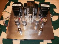
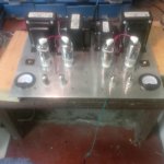
Just set up another red board and cannot say enough about the quality and ease to make this bad boy work. Just to make it look great I put a couple of amp gauges on it but I am unsure where to connect them. I could connect them with a three way toggle to set each of the parameters but again Pete asks for measurements in millivolts and I am unsure how to attach them for milliamps. Hope my build looks good. I will break it in and then put it in the mahogany case after I figure out how much airflow it will need.
Attachments
Wow, this thread has been quiet for almost a year.😱 Anyone building an amp? Screen drive version perhaps?😀
jeff
jeff
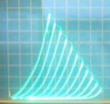
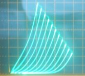
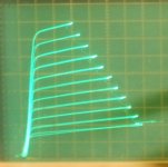
Here are the Schade curves for the 6JN6 (6GE5, 6GV5, 6FW5, 6DQ6B):
http://www.diyaudio.com/forums/tubes-valves/271134-schade-cfb-exactly-equivalent-5.html#post4259063
More Schade curves for other tubes coming up.
http://www.diyaudio.com/forums/tubes-valves/271134-schade-cfb-exactly-equivalent-5.html#post4259063
More Schade curves for other tubes coming up.
Re-using transformer
Glad that this thread is alive again. I have some questions for a stock build using 6cb6 and 6jn6:
1) I intend to re-use my old broken el34 tube amp power transformer with the following specs:
0-320v x 2 @ 130ma each
0-15v x 2 @ 130ma each
0-6.3v 2 x @ 3amp each
Intend to connect the HV and filament wires 2 x secondary in series to create a CT needed for the board.
Will purchase a separate 50v-0-50v 20ma as recommend on schematic for the bias supply.
With this transformer do i need to increase the size of R21 to maybe 10W as they need to work harder to drop the voltage for the regulator? or do i need a larger value for R21 like 5.6k instead of 4.7k to drop more voltage?
Increasing R51 and R53 size? sorry I'm not good with the maths so i cannot determine if 2W is sufficient.
I think i will take the risk that the voltage will be pretty close to the 450v cap limit. (Punishment for ordering parts before finish reading the thread) and also its pretty close to 6JN6 plate dissipation limit.
And lastly is there any other components that i need to change so as not to make the the amp only lasting me 1 month. 😀
Or its better for me to custom wind another transformer with the exact spec. (Edcor is not expensive but shipping is for me)
Thank you for reading and hope to get some advice on this!
Intending to take this on in the coming year. I've been reading Pete's page for quite a while now.
Another way to keep in the smoke is to use a Variac for initial powerup... per the author. Cheers!
I have been running 42kn6 in many amps for over 20 years. They are the ultimate power tube. Period. In push pull they easily do 150 watts. The cathode is capable of delivering so much current that one doesn't have to bother with taps on the secondary. They are like transistors. Then the enhanced triode circuit came out and that sealed the deal.
They are the ultimate power tube. Period.
I have stuffed 6KN6's into Petes red board. They do kick butt, but "ultimate. Period" maybe not....it's all about what you are trying to achieve. I will still call the 6LW6 the ultimate sweep tube.
Note, that there are two totally different tubes called "KN6.
One is a typical big sweep tube with a single structure inside. They work well in both audio and RF amplifiers, hence are somewhat scarce and expensive.
The other has TWO smallish sweep tube guts inside a common envelope, wired in parallel. These do NOT work well in RF amps, and if the seller understands this, can often be had for a reasonable price. These will actually support higher peak cathode currents than the single plate variety, but can dissipate lower overall power since the area between the plates can not shed its heat leading to hot spots. Many of the Sylvanias produced near the end of the vacuum tube area also have alignment problems, also causing hot spots at high average dissipations.
I have some of both, and each will easily make 150 WPC in this amp, but a good set of the twin plate variety sounds better to me on highly dynamic music played loudly through big speakers.
"Then the enhanced triode circuit came out and that sealed the deal."
You mean g2 drive? Or Schade configuration?
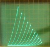
Here is a way to do both at once:
http://www.diyaudio.com/forums/tubes-valves/271134-schade-cfb-exactly-equivalent-11.html#post4279626
1) Schaded g1 drive + direct g2 drive (21HB5A)
2) usual Schaded g1 drive (21HB5A)
3) "triode" configured (21HB5A)
4) g2 drive only (21HB5A)
You mean g2 drive? Or Schade configuration?
Here is a way to do both at once:
http://www.diyaudio.com/forums/tubes-valves/271134-schade-cfb-exactly-equivalent-11.html#post4279626
1) Schaded g1 drive + direct g2 drive (21HB5A)
2) usual Schaded g1 drive (21HB5A)
3) "triode" configured (21HB5A)
4) g2 drive only (21HB5A)
Attachments
- Home
- Amplifiers
- Tubes / Valves
- Posted new P-P power amp design