I've run in triode and ultralinear mode (those measurements were UL). You could certainly run pentode as well - I don't think I measured that yet.
I've been using E80L pentodes as the driver - I'll try 12BY7A next. Using a 6J5/8532 input tube, with gNFB to the cathode.
This board will be more flexible than the big red board. Only the input and driver - for one channel - on the PCB. No power supply or other components. You can also apply local feedback from the output tube plates, or ultralinear taps, to the driver plate. So you can set it up in a number of different ways, and use whatever output tube(s) you want.
I just ordered proto PCBs, so it'll be a little while yet. I might try and post some early info on the web site in the next couple of weeks.
Pete
Nice Pete, I'll be looking for it.
And like Tubelab mentioned if you use a certain pinout for the driver there is
a whole host of tubes that could go in there.
Using an "6EJ7 as yur driver layout" with pin 1 as the cathode opens it on up.
(sure I'm not telling you anything you don't know, but just for reference)
Obviously pin 3 works if you want E80L an 6EJ7, otherwise yah 1 with 12BY7
and 6EJ7, but I'm sure you've looked an there are "many" use 1 or the other.
There's an list of tubes I posted on here somewhere with quite a few of them.
Last edited:
I'm still having driver tubes issues, after picking up a couple more yesterday, I can only get one channel to balance. And that's the channel that hums. The JAN Philips 6BZ6's just aren't cutting it.
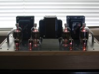
I really went "all out" for this build.😉 Wood chassis is recycled from our old kitchen cabs, heat-sink is from a dead 80's Sansui R-30 receiver, and the handles are from Ikea. I just need to get some socket head cap screws for the top plate and put some oil on the wood.😀
jeff
I really went "all out" for this build.😉 Wood chassis is recycled from our old kitchen cabs, heat-sink is from a dead 80's Sansui R-30 receiver, and the handles are from Ikea. I just need to get some socket head cap screws for the top plate and put some oil on the wood.😀
jeff
Attachments
I'm still having driver tubes issues, after picking up a couple more yesterday, I can only get one channel to balance. And that's the channel that hums. The JAN Philips 6BZ6's just aren't cutting it.
I really went "all out" for this build.😉 Wood chassis is recycled from our old kitchen cabs, heat-sink is from a dead 80's Sansui R-30 receiver, and the handles are from Ikea. I just need to get some socket head cap screws for the top plate and put some oil on the wood.😀
jeff
Looks really nice, Jeff!
Hey thanks! Amp doesn't sound too bad in the main system, despite the driver issues. For most music, I don't miss having the sub connected. Really good bass, even with the small speakers.
jeff
jeff
I would really like to see pete's new design be "universal" enough to adequately drive the new kt120s
Some suggest they might actually sound better than kt88s
Alex
Some suggest they might actually sound better than kt88s
Alex
Last edited:
I would really like to see pete's new design be "universal" enough to adequately drive the new kt120s
Some suggest they might actually sound better than kt88s
Alex
I would expect it could... being "universal", part of that might be up to you!
I just posted some info on it here: Push-pull driver board
I have prototypes in fab, but can make changes before a "production" run.
Pete
Would I be pushing it if I were to ask you for a GU81M compatibile amplifier?
😀
GU81M / GU-81M / GU81 / GU-81 / GU80 / GU-80
😀
GU81M / GU-81M / GU81 / GU-81 / GU80 / GU-80
Just in case anyone is interested - I have parts for this amp up for sale here:
http://www.diyaudio.com/forums/swap-meet/202890-fs-parts-dcpp.html
I purchased them around this time last year but never got around to actually building the thing.
http://www.diyaudio.com/forums/swap-meet/202890-fs-parts-dcpp.html
I purchased them around this time last year but never got around to actually building the thing.
Last edited:
Hi All,
Just completed my DCPP build, 100% stock apart the "surrounding things".
Turned the amp into a remote controlled integrated amp using a motorized Alps RK27 driven by a small DIY card I bought from Dantimax. Input selection is done by a two pole alps selector; this one by hand ..😛
The card driving the pot motor also has two relay ouputs I used to connect/disconnect NFB and put on/off the B+...
Everythings works more than fine and I'm really pleased with the sound. Got no hum at all at any level on my 89,5dB speakers, and I find the details and dynamics just amazing! I have more than enough output, I usually ran the amp with the pot @ 9hours...
The chassis work is 100% custom made, Top/bottom plates bent and laser cut from 3mm aluminum plates, front/back plates machined out of solid aluminum, painted and then laser engraved. Feets and buttons are machined from solid Teflon plastic.
I have all the drawings of everything if someone is interrested 😉


Thank you very much for your work Pete!
Just completed my DCPP build, 100% stock apart the "surrounding things".
Turned the amp into a remote controlled integrated amp using a motorized Alps RK27 driven by a small DIY card I bought from Dantimax. Input selection is done by a two pole alps selector; this one by hand ..😛
The card driving the pot motor also has two relay ouputs I used to connect/disconnect NFB and put on/off the B+...
Everythings works more than fine and I'm really pleased with the sound. Got no hum at all at any level on my 89,5dB speakers, and I find the details and dynamics just amazing! I have more than enough output, I usually ran the amp with the pot @ 9hours...
The chassis work is 100% custom made, Top/bottom plates bent and laser cut from 3mm aluminum plates, front/back plates machined out of solid aluminum, painted and then laser engraved. Feets and buttons are machined from solid Teflon plastic.
I have all the drawings of everything if someone is interrested 😉
Thank you very much for your work Pete!
Hi All,
Just completed my DCPP build, 100% stock apart the "surrounding things".
Turned the amp into a remote controlled integrated amp using a motorized Alps RK27 driven by a small DIY card I bought from Dantimax. Input selection is done by a two pole alps selector; this one by hand ..😛
The card driving the pot motor also has two relay ouputs I used to connect/disconnect NFB and put on/off the B+...
Everythings works more than fine and I'm really pleased with the sound. Got no hum at all at any level on my 89,5dB speakers, and I find the details and dynamics just amazing! I have more than enough output, I usually ran the amp with the pot @ 9hours...
The chassis work is 100% custom made, Top/bottom plates bent and laser cut from 3mm aluminum plates, front/back plates machined out of solid aluminum, painted and then laser engraved. Feets and buttons are machined from solid Teflon plastic.
I have all the drawings of everything if someone is interrested 😉
Thank you very much for your work Pete!
Awesome job Rimb! I like that box a lot.
Would I be pushing it if I were to ask you for a GU81M compatibile amplifier?
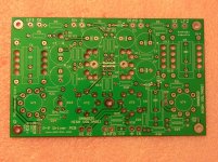
I think this circuit, if set up right, can do that! In class A/AB1, anyway, not A/AB2.
In pentode mode using 12GN7's, you should be able to get over 140V peak or 280V grid-to-grid with a zout of ~5k.
Here's a picture of the prototype PCB. Schematic is on my web site.
Pete
Attachments
Awesome job Rimb! I like that box a lot.
Thanks patkhan 🙂
By the way, I have a question: I had to rewire some things that doesn't appear in my picture to have my amp working as I wanted to. Basically on the picture my pilot lights are wired in parrallel on the relay outputs of the small remote PCB. They were dragging too much current and my relays wouldn't work. So I had to wire them directly onto the small 5-0-5v transformer I've added, trough the relays. For the NFB no problem as I had two spare contacts. But on the other one, which is wired in the picture so as to cut both 280v and 50V taps out of the xfmr, I had to remove the 50v taps and put my pilot lamp instead.
So now I have a relay that can switch the 280V on /off while the rest stays alive.
I was wondering if this could be harmful for the amp?
I think this circuit, if set up right, can do that! In class A/AB1, anyway, not A/AB2.
In pentode mode using 12GN7's, you should be able to get over 140V peak or 280V grid-to-grid with a zout of ~5k.
Here's a picture of the prototype PCB. Schematic is on my web site.
Pete
Very nice! Ignorant as I am I ony just noticed the bias section needs to be modified for 200 - 220vac operation.
I am actually stuck on how to best use your 12HG7 pentode in triode mode, using a lundhal interstage transformer for phase splitting http://www.lundahl.se/pdfs/datash/1620_3_7.pdf, strapping the GU81ms in PP triodes and using a Hammond 1650R - good for 100w RMS - and praying to the the heavens I don't kill myself in the process 🙂
Anyways, as soon as you will have some PCB for sale I'll be a customer.
Alex
I think this circuit, if set up right, can do that! In class A/AB1, anyway, not A/AB2.
In pentode mode using 12GN7's, you should be able to get over 140V peak or 280V grid-to-grid with a zout of ~5k.
Here's a picture of the prototype PCB. Schematic is on my web site.
Pete
Hm...I'm thinking three channel 7355 P-P power stage using Bogen iron. Whaddaya think?
Hm...I'm thinking three channel 7355 P-P power stage using Bogen iron. Whaddaya think?
Sure, why not? Lots of options... 2 stage or 3, NFB, local feedback...
Pete
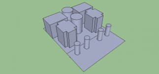
I think I finally came up with a top plate for my amp. I was trying to come up with a solution that would allow all four transformers as well as the large ASC caps all on one chassis. I need to work on my Sketchup skills but they are coming along. Total top plate measures 13.5" x 18". I have some 1/8" aluminum and I plan to add some bracing on the underside to help carry the load.
Attachments
Small update. I finally ordered my board components. Got the board half populated now, I'll finish it this week. Don't have trannies or case yet but at least it's some progress.
Which of the caps that are part of the power supply would provide the most benefit if upgraded to PIO motor run caps? I would think that C2, C3, C24 and C27 would be the best candidates for the substitution but I am not sure. What about C21 and C25?
I have searched this thread but didn't come up with anything on this issue, so if this has come up and covered in the past, I apologize in advance.😱
I have searched this thread but didn't come up with anything on this issue, so if this has come up and covered in the past, I apologize in advance.😱
- Home
- Amplifiers
- Tubes / Valves
- Posted new P-P power amp design