lineup solid state dsicrete 3 pin regulator
🙂
A follow up to my Post #14 in this topic.
Where I show a close up of my most advanced headphone amp circuit.
You can see itin this Image Attachment:
http://www.diyaudio.com/forums/attachment.php?s=&postid=1134699&stamp=1171426328
========================
This time,
I will put ..... a small very precise 3 pin regulator
built with 3 TO-92 transistors + some diodes for voltage reference.
Intended use: Powering Op-Amps in battery powered gear.
Data:
Circuit own power consumption: 150uA ( 0.000150 Ampere )
Voltage output: +5.000 Volt ( +/- 0.010 Volt = 10mV )
Max current output: ~50-100 mA something
(but few normal audio Op-Amps would take more than 10mA per IC)
Dropout Voltage: ~0.050 Volt max (at 'normal' 15-25mA output)
... gives ...
Minimum input voltage( for +4.99V out): 5.04 Volt DC ... 😎
As said, this regulator, in it self would take, draw, only 0.15 mA to work properly.
So it would take many months to empty your batteries.
----------------------------------
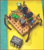
The hardware use the same typical ' lineup costruction method '
= hardwire at the bottom side of a piece of pcb experiment board.
In this case, it required like 25x25mm (1x1 inch)
See image attached here below.
It is easy to see my 3 brown pins in the corners of my circuit:
1. input pin
2. ground - 0 Volt pin
3. output pin
Regards and happy viewing my nice picture!
And my good design works!
😎
lineup
🙂
A follow up to my Post #14 in this topic.
Where I show a close up of my most advanced headphone amp circuit.
You can see itin this Image Attachment:
http://www.diyaudio.com/forums/attachment.php?s=&postid=1134699&stamp=1171426328
========================
This time,
I will put ..... a small very precise 3 pin regulator
built with 3 TO-92 transistors + some diodes for voltage reference.
Intended use: Powering Op-Amps in battery powered gear.
Data:
Circuit own power consumption: 150uA ( 0.000150 Ampere )
Voltage output: +5.000 Volt ( +/- 0.010 Volt = 10mV )
Max current output: ~50-100 mA something
(but few normal audio Op-Amps would take more than 10mA per IC)
Dropout Voltage: ~0.050 Volt max (at 'normal' 15-25mA output)
... gives ...
Minimum input voltage( for +4.99V out): 5.04 Volt DC ... 😎
As said, this regulator, in it self would take, draw, only 0.15 mA to work properly.
So it would take many months to empty your batteries.
----------------------------------
The hardware use the same typical ' lineup costruction method '
= hardwire at the bottom side of a piece of pcb experiment board.
In this case, it required like 25x25mm (1x1 inch)
See image attached here below.
It is easy to see my 3 brown pins in the corners of my circuit:
1. input pin
2. ground - 0 Volt pin
3. output pin
Regards and happy viewing my nice picture!
And my good design works!
😎
lineup
Attachments
Hi lineup,
I have always loved your breadboarding. It reminds me my schooldays, when I started with electronics.
Go on!
Regards,
Pavel
I have always loved your breadboarding. It reminds me my schooldays, when I started with electronics.
Go on!
Regards,
Pavel
PMA said:Hi lineup,
I have always loved your breadboarding. It reminds me my schooldays, when I started with electronics.
Go on!
Regards,
Pavel
Thanks
...
Here you have my discrete regulator data again .. in case somebody did miss it.
Transistors are BC550C and BC560C .. no other could do this job better, at such price.
A Feature worth mentioning:
Reference diodes, see picture: 1N4148 + Green LEDs
This reference is powered, biased
from my very precise OUTPUT ( +/- 0.01 Volt )
This feature, of course, improves 🙂
Regulator Line Regulation enormously! 🙂
Think these data deserves to be noted:
----------------------------------------------------------------------
Data:
Circuit own power consumption:
150uA ( 0.000150 Ampere )
Voltage output:
+5.000 Volt ( +/- 0.010 Volt = 10mV ), accuracy +/- 0.2%
Max current output:
~50-100 mA something
(but few normal audio Op-Amps would take more than 10mA per IC)
Dropout Voltage: ~0.050 Volt max
(at 'normal' 15-25mA output)
... gives ...
Minimum input voltage( for +4.99V out):
5.04 Volt DC ...
----------------------------------------------------------------------
... those figures can take a compare
against 97.5% of all commercial chips out on the market
😉
lineup
--------------------------------------------------------------
[color=sea-green]PMA
You use your turntable?
I have plenty of very good old LP vinyl albums.
Have been thinking of
- Build myself a good discrete RIAA amp
- Upgrade my Pickup to something nice
- Start copy my analog LP Records to Digital CD
..... but typical for me is this thinking:
"Hmm, there is a day tomorrow, too.
I will do this Vinyl Project later"
[/color]
... and as we all know, tomorrow ALSO has got a day tomorrow ... => into infinity
but for us, human souls, comes a day, sooner or later,
when there is no more tomorrows

Hi lineup,
yes, I still use my turntable with Shure cartridge. The RIAA pre is active, based on 2134. And I have a nice collection of LPs, and time after time I buy new presses in 180 grams.
I am afraid that digitalization of LPs makes the worst of both worlds, containing disadvantages of both media ... you get LP noise + digital sound (low sampling speed, bad digital filters and HF residuals).
Regards,
Pavel
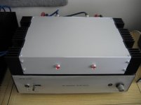
My little power amp
Here's my entry:
Dual mono lateral MOSFET amp, with JFET input stage and mainly SMD construction. Each channel is good for 140W RMS into 8 Ohms. 0.0013% THD (1KHz, 100W into 8 Ohms).
It's been running for a goodly few months now, with its matching preamp. I still haven't gotten around to building a muting circuit for it though, and it's still without a front panel
It sounds good though 🙂
Here's my entry:
An externally hosted image should be here but it was not working when we last tested it.
Dual mono lateral MOSFET amp, with JFET input stage and mainly SMD construction. Each channel is good for 140W RMS into 8 Ohms. 0.0013% THD (1KHz, 100W into 8 Ohms).
It's been running for a goodly few months now, with its matching preamp. I still haven't gotten around to building a muting circuit for it though, and it's still without a front panel
It sounds good though 🙂
Member
Joined 2002
Re: My little power amp
Looks very nice, who's design ? Good job 🙂
suzyj said:Here's my entry:
An externally hosted image should be here but it was not working when we last tested it.
Dual mono lateral MOSFET amp, with JFET input stage and mainly SMD construction. Each channel is good for 140W RMS into 8 Ohms. 0.0013% THD (1KHz, 100W into 8 Ohms).
It's been running for a goodly few months now, with its matching preamp. I still haven't gotten around to building a muting circuit for it though, and it's still without a front panel
It sounds good though 🙂
Looks very nice, who's design ? Good job 🙂
Re: Re: My little power amp
It's an updated version of David Tilbrook's AEM6000. See http://www.littlefishbicycles.com/poweramp/index.html for details.
Basically I used his topology, but updated a many of the transistors, then used spice to optimise everything to get the distortion figures down.
jleaman said:
Looks very nice, who's design ? Good job 🙂
It's an updated version of David Tilbrook's AEM6000. See http://www.littlefishbicycles.com/poweramp/index.html for details.
Basically I used his topology, but updated a many of the transistors, then used spice to optimise everything to get the distortion figures down.

Member
Joined 2002
Re: Re: Re: My little power amp
What simulation software did you use if i may ask ?
I'm learning Electronic Work Bench, but the library files are not that large, i can;t get IRF fet's and other things that i'm used to using.
Great chassis work and good layout. Protel is nice..
Jase
suzyj said:
It's an updated version of David Tilbrook's AEM6000. See http://www.littlefishbicycles.com/poweramp/index.html for details.
Basically I used his topology, but updated a many of the transistors, then used spice to optimise everything to get the distortion figures down.
What simulation software did you use if i may ask ?
I'm learning Electronic Work Bench, but the library files are not that large, i can;t get IRF fet's and other things that i'm used to using.
Great chassis work and good layout. Protel is nice..
Jase
Member
Joined 2002
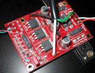
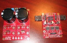
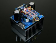
Here is a close up picture of the SMD amplifiers that i am running.
J'
http://www.jasesspace.com/G2/main.php?g2_itemId=352
J'
http://www.jasesspace.com/G2/main.php?g2_itemId=352
jleaman - SMD Mini Aleph
jleaman - SMD Mini Aleph
Interesting!
😎
Deserves to be shown. Something for others to build, too ... ?
Photo 1 (from jleaman's public 'Audio Stuff' gallery (see link above )
jleaman said:Here is a close up picture of the SMD amplifiers that i am running.
http://www.jasesspace.com/G2/main.php?g2_itemId=352
🙂
jleaman - SMD Mini Aleph
Interesting!
😎
Deserves to be shown. Something for others to build, too ... ?
Photo 1 (from jleaman's public 'Audio Stuff' gallery (see link above )
Attachments
Nordic said:I'd love that in a kit hey.
Nordic
Those Mini Aleph PCB are available, I think.
Because, Looking closely at the boards, after posting,
I could read 'BrianGT' in a corner ..
Now he is most know for making great 😎 Gainclone boards
for National chips like LM3875, LM3886 and LM4780.
( Explore / Order here: http://www.chipamp.com/ )
I would go search the forum for BrianGT Mini Aleph
Mini Aleph PCB may be mentioned somwhere ...
Anyway, when jleaman comes around to see my posts
He will give us more info 🙂
... how to get those boards
Regards
lineup, Lineup Audio Sevices
http://lineup.awardspace.com
🙂
Member
Joined 2002
jleaman said:
They are in kit's.
Jase
hi, newbie here. where can one get those kits from and how much do they cost?
🙂
Arlo,
my god, that one is not an amplifier:
...................
cause is
an 2SC2922
work of art
...................
Arlo Mono Amp Creation!
http://www.ampslab.com/trans_2sc2922.htm
Japanese SC2922 Sanken ==> $30.00 for 4 pieces (paypal)
😎
lineup
😎
Arlo,
my god, that one is not an amplifier:
...................
cause is
an 2SC2922
work of art
...................
Arlo Mono Amp Creation!
http://www.ampslab.com/trans_2sc2922.htm
Japanese SC2922 Sanken ==> $30.00 for 4 pieces (paypal)
😎
lineup
😎
- Home
- Amplifiers
- Solid State
- Post your Solid State pics here