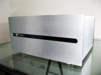
Amazing work MJL21193!! 😱
I remember seeing the thread on it's construction but I must have lost track of it at some point. Great to see it finished so beautifully 🙂
I remember seeing the thread on it's construction but I must have lost track of it at some point. Great to see it finished so beautifully 🙂
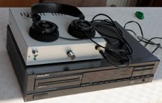
Controller
This is a fun project
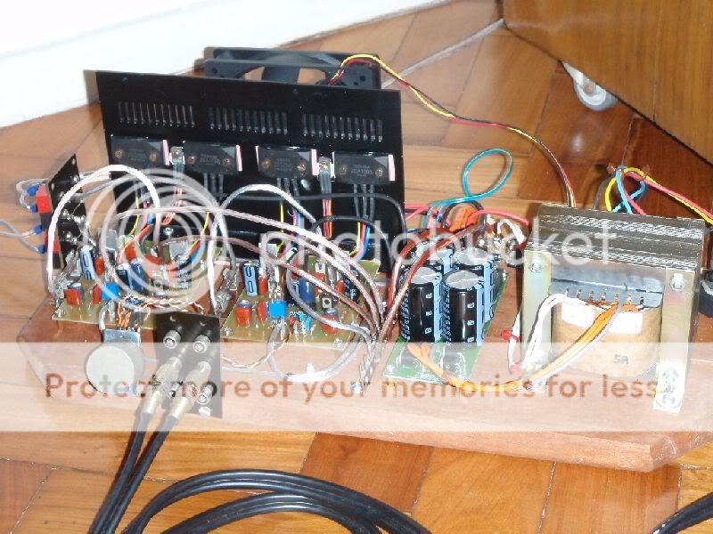
Atmel based audio controller... Does everything, from power up/down sequencing, to supervising and displaying the heatsinks temperatures, power supplies, output offset, bar graph VUMeter, overload protection, clipping indicator, and allowing the YAP 2.1 amp to be remote controlled over an I2S link.
Now writing drivers for various devices, temperature is ready (Maxim DS18B20), display is ready, VUMeter is in the works... Will be single board and most likely Atmega1281 based. A few general purpose opamps for signal conditioning and tons of interrupt driven software. And including a bootloader to allow software upgrades over a serial link.
This is a fun project
Atmel based audio controller... Does everything, from power up/down sequencing, to supervising and displaying the heatsinks temperatures, power supplies, output offset, bar graph VUMeter, overload protection, clipping indicator, and allowing the YAP 2.1 amp to be remote controlled over an I2S link.
Now writing drivers for various devices, temperature is ready (Maxim DS18B20), display is ready, VUMeter is in the works... Will be single board and most likely Atmega1281 based. A few general purpose opamps for signal conditioning and tons of interrupt driven software. And including a bootloader to allow software upgrades over a serial link.
Attachments

Last edited:
I also use a controller for housekeeping on my amp - really beats going analog. I do power on/off including in-rush current control, temperature, clipping and DC offset. I ended up using an NXP controller (89lpc922). I did everything in 'C' and ended up with about 1.5k of code. Good luck with your board.
I also use a controller for housekeeping on my amp - really beats going analog. I do power on/off including in-rush current control, temperature, clipping and DC offset. I ended up using an NXP controller (89lpc922). I did everything in 'C' and ended up with about 1.5k of code. Good luck with your board.
Would you share some of what you did to get to this, I would and I am certain others would be keen to see what you have done in this direction of Control, THANKS for the thoughts.....
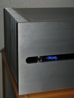
This is my Symasym, with better parts, sounds wonderful,
as you can see in youtube
http://www.youtube.com/watch?v=XFbsolcxf0E
http://www.youtube.com/watch?v=IKOhm...e=channel_page
best regards
hcbonfim
as you can see in youtube
http://www.youtube.com/watch?v=XFbsolcxf0E
http://www.youtube.com/watch?v=IKOhm...e=channel_page
best regards
hcbonfim
Attachments
Hi,
after a long time I will try it again posting pictures of my F5-clone.
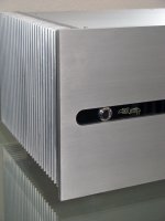
Bravo 400 for your effort. It is obvious that all the machining work of the amplifier case has been made by your hands in home. The front panel especially it looks great. It must you have spent enough time for the sanding work. The cutting of the decorative line (very nice) in the middle of panel, must be done with milling machine.
In fact, such type projects which are REAL DIY PROJECTS made by hands, few home tools and many labour, they express the ingenuity, the inventiveness, the craftsmanship and the artistic view of the REAL DIYer .
Please, give a warm applause in 400!
Fotios
Thanks Fotios.
Yes, the line in the middle I have done with a small milling machine.
The aluminium sheets I have cutted with a buzz saw.
Sanding by hand with wet abrasive paper (it takes some time...)
Lot of work, but it is great to do the vast bulk of the amp myself!
Thanks to all showing their projects here. I have got much ideas and stimulations from here.
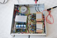
heatsink big enough ?
Kip , for a sealed plexiglass enclosure , that is about right for 2 X 15w class B. BtW , real cool, exbrayat... 😎
Some of us excessive fanatics
, with the kilowatt amps, need heatsinks big enough to cool off ovens !! (attachment) That one is 2 X 21" X 7" X 4 " 😱It really is better to have too much than too little (Gm doubling / shorter component life).
OS
Attachments
It seems enough. The plexy plates are disjointed and permit air cooling in the amp. And 15W is a little power in class-B...heatsink big enough 😱
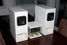
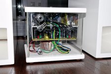
I like slim line!
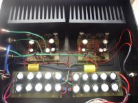
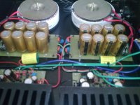
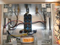
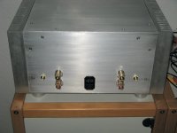
Pictures of the revised amplifier Charisma 0K6 (see in post 713 the initial design and why the revision). I must point out that everything in this project it is designed, constructed and machined in my home with my hands except the heatsinks and the transformer.
IT IS AN ABSOLUTE DIY PROJECT.
Regs
Fotios
Pictures of the revised amplifier Charisma 0K6 (see in post 713 the initial design and why the revision). I must point out that everything in this project it is designed, constructed and machined in my home with my hands except the heatsinks and the transformer.
IT IS AN ABSOLUTE DIY PROJECT.
An externally hosted image should be here but it was not working when we last tested it.
An externally hosted image should be here but it was not working when we last tested it.
An externally hosted image should be here but it was not working when we last tested it.
An externally hosted image should be here but it was not working when we last tested it.
An externally hosted image should be here but it was not working when we last tested it.
An externally hosted image should be here but it was not working when we last tested it.
An externally hosted image should be here but it was not working when we last tested it.
An externally hosted image should be here but it was not working when we last tested it.
An externally hosted image should be here but it was not working when we last tested it.
Regs
Fotios
Last edited:

Thanks John
Indeed, i have spent 6 months to finish it.
I am really very satisfied and not because the success of project. I am very satisfied because i have not paid neiter one Euro, be it so counterfeit, to any VAMPIRE machinist, pcb constructor or graphic artist!
That is the real pleasure!
Regs
Fotios
Indeed, i have spent 6 months to finish it.
I am really very satisfied and not because the success of project. I am very satisfied because i have not paid neiter one Euro, be it so counterfeit, to any VAMPIRE
machinist, pcb constructor or graphic artist! That is the real pleasure!
Regs
Fotios
Pictures of the revised amplifier
.
IT IS AN ABSOLUTE DIY PROJECT.
Regs
Fotios
Well, looks better than most commercial amps
- Home
- Amplifiers
- Solid State
- Post your Solid State pics here