So there's something wrong with all this because when I measured the power, I used a 1KHZ sinusoidal signal and the heat sink got hot, but not to the point where I couldn't touch it with my hands.
During the auditions, he gets warm, except one day when I decided to turn the music very loud. This day he got a lot hot but nothing to worry about. I found the temperature quite normal considering being an AB amplifier.
Anyway, I will exchange the power transformer for one capable of providing 350W.
Maybe with this 350W power transformer the heating will be too high?
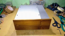
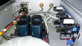
Below the specifications of each heatsink.
Heatsink Dimensions: 110mm x 260mm, thickness is 7mm,
Each heatsink has a net weight of 0.8 kg.
Soja, with a 350W transformer and the same voltage, you effectively still only have a 70W (8 Ohm) amplifier. You might get away with the cooling as is for that, but on 4 Ohm, I would worry about over heating. I'd guesstimate you might get about 110W out of it on 4 Ohm, as is but too much heat would be an issue, I'd think.
But I could be wrong.
Below the specifications of each heatsink.
Heatsink Dimensions: 110mm x 260mm, thickness is 7mm,
Each heatsink has a net weight of 0.8 kg.
Is it a finned heat sink ?
Soja, with a 350W transformer and the same voltage, you effectively still only have a 70W (8 Ohm) amplifier. You might get away with the cooling as is for that, but on 4 Ohm, I would worry about over heating. I'd guesstimate you might get about 110W out of it on 4 Ohm, as is but too much heat would be an issue, I'd think.
But I could be wrong.
But with a 350W power transformer versus a 240W power transformer I would have lower voltage drop. Or am I wrong?
Measuring at 1Khz sine wave and 4ohms load the power supply voltage dropped from 42V to 36V.
I imagine that with a higher current power transformer, I have lower voltage drop.
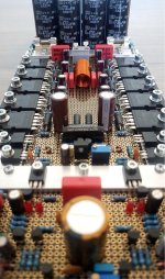
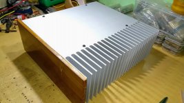
Is it a finned heat sink ?
Yes, with fins.
See the photo of the heatsink.
Attachments


But with a 350W power transformer versus a 240W power transformer I would have lower voltage drop. Or am I wrong?
Measuring at 1Khz sine wave and 4ohms load the power supply voltage dropped from 42V to 36V.
I imagine that with a higher current power transformer, I have lower voltage drop.
Yes, the voltage drop of the bigger transformer will likely be less, but you still have difficult to predict voltage drops elsewhere, as in the rectifier, traces, wires and bond wires which will all impact more the lower the load impedance is.
But that is not really a concern, it's more of a given. The concern is possibly overheating when operating at rated power and/or lower load impedance.
The ribs on the heat sink seem, just by the looks of it with respect to your proposed power rating, a little bit under-engineered.
But, I could be wrong.
Truth. You're right.
I have sized the connection cables to prevent or minimize potential current losses through undersized cabling. But I don't know what parameters the board layout designer took into consideration when sizing his tracks.
Currently, the nominal impedance of my speakers is 6 ohms and I do not intend to use speakers with a nominal impedance lower than this.
As for heatsinks, really their fins are not as large as they could be.
Therefore, I will not abuse high volume and impedances of less than 6 ohms.
These days, during my auditions, the heatsinks are comfortably warm and no more. In this way I hope this amplifier has a long life.
Thank you so much for your answers, It's been great for me to know other points of view and enhance my knowledge
Thank you!
Ps: What are these gadgets on your avatar? I got curious. 🙂
Last edited:
Truth. You're right.
I have sized the connection cables to prevent or minimize potential current losses through undersized cabling. But I don't know what parameters the board layout designer took into consideration when sizing his tracks.
Currently, the nominal impedance of my speakers is 6 ohms and I do not intend to use speakers with a nominal impedance lower than this.
As for heatsinks, really their fins are not as large as they could be.
Therefore, I will not abuse high volume and impedances of less than 6 ohms.
These days, during my auditions, the heatsinks are comfortably warm and no more. In this way I hope this amplifier has a long life.
Thank you so much for your answers, It's been great for me to know other points of view and enhance my knowledge
Thank you!
Ps: What are these gadgets on your avatar? I got curious. 🙂
Just keep an eye on the operating temperature and you will be ok.
Well, the gadget you are referring to is my little headphone amplifier I build about 10 years ago.
If this interests you, here are a few pictures of the building process.🙂
.
The all new and improved HPA - My Photo Gallery
Last edited:
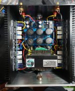
The amplifier housing . Not yet completed
Attachments


Last edited:
The amplifier housing . Not yet completed
Nice Work!
Last edited:
Nice Work!
Checked your headphone amp too ... Really Nice.
The power amplifier is also original.
The project is joint with Dmitry Vikulov
Last edited:
Just keep an eye on the operating temperature and you will be ok.
Well, the gadget you are referring to is my little headphone amplifier I build about 10 years ago.
If this interests you, here are a few pictures of the building process.🙂
.
The all new and improved HPA - My Photo Gallery
Man, what a beautiful device!
All made with great care!
Congratulations on creating and assembling
Thanks. I am quite happy with it. Originally it started as a HPA 1.0 by gmarsh.
My latest project - DAC + headphone amp
The amplifier was essentially bare bones and only had a coax SPDIF input. I had just joined the forum and was intrigued by it and proposed a pimped up version of it with more inputs and stuff, people were all happy with it as is so the interest in my proposal was exactly ZIP, NILCH, NADA....
To this day I am not sure why.
PCB Group Buy for the "DAC + headphone amp" Project
So I ended up massaging it to my liking and build two units. One for myself and the other for my friend.
I added a few extra features such as, QTouch, IR remote, motorized volume control with quadrature encoder, LCD display, VU Meter, TOSLINK in- and outputs, USB input (altho only 16bit).
This headphone amplifier makes an amazing combo with Denon headphones. Crystal clear highs and a massive bass... 😀😀😀
I had posted some pictures on page 177 of this thread, centuries ago...😀😀😀
.
Thanks. I am quite happy with it. Originally it started as a HPA 1.0 by gmarsh.
My latest project - DAC + headphone amp
The amplifier was essentially bare bones and only had a coax SPDIF input. I had just joined the forum and was intrigued by it and proposed a pimped up version of it with more inputs and stuff, people were all happy with it as is so the interest in my proposal was exactly ZIP, NILCH, NADA....
To this day I am not sure why.
PCB Group Buy for the "DAC + headphone amp" Project
So I ended up massaging it to my liking and build two units. One for myself and the other for my friend.
I added a few extra features such as, QTouch, IR remote, motorized volume control with quadrature encoder, LCD display, VU Meter, TOSLINK in- and outputs, USB input (altho only 16bit).
This headphone amplifier makes an amazing combo with Denon headphones. Crystal clear highs and a massive bass... 😀😀😀
I had posted some pictures on page 177 of this thread, centuries ago...😀😀😀
.
Very cool your work!
I still get to that level!
Thanks mate.
Alto working free hand with 0805 and stuff is not really fun anymore, at least for me as my sight is deteriorating and I am due for a new set of stronger glasses.
Alto working free hand with 0805 and stuff is not really fun anymore, at least for me as my sight is deteriorating and I am due for a new set of stronger glasses.
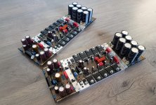
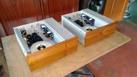
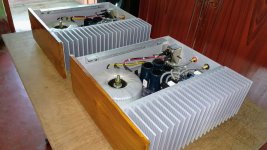
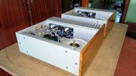
Monoblocks based on the V4H, just finished.
No CNC yet. All cuts in the chassis made by hand (with the help of a wood router). Plain anodized body and teak front.
No CNC yet. All cuts in the chassis made by hand (with the help of a wood router). Plain anodized body and teak front.
Attachments
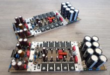
Monoblocks based on the V4H, just finished.
No CNC yet. All cuts in the chassis made by hand (with the help of a wood router). Plain anodized body and teak front.
Beautiful.
Beautiful, but why not symmetrical blocks?
Beautiful.
Beautiful, but why not symmetrical blocks?
Thanks.
Both channels were made the same in order to simplify the build and decrease the chance of misaligned screw holes.
- Home
- Amplifiers
- Solid State
- Post your Solid State pics here