So you're saying you don't know that a vented box is a Helmholtz resonator nor how it works?You give me too much credit, Scott. 🙂 I don't know the answer.
From what process does the pipe resonance (based on the length of the port) take its energy? My post #39 tells where I'm going with this.
It's the air mass 'spring' (Vb) the driver, vent tube is 'attached' to. Note too that the pipe's effective diameter sets its HF cut-off or in organ pipe jargon, where it no longer 'speaks'.
Just trying to find out whether damping material in the box or something else will deal with the pipe resonance?
Expected to be typically above the bass range. If the box is bigger than the pipe then can't we expect a modal coupling that can be more easily managed?
Expected to be typically above the bass range. If the box is bigger than the pipe then can't we expect a modal coupling that can be more easily managed?
OK, sure in that it lowers pipe Q. Better to critically damp the vent though unless wanting to make it somewhat aperiodic.

You plan to have the speakers placed at the wall, this will do really bad things to the sound, and you are concerned to a hypothetically midrange leakage of a front port? What is the design you plan to build, and how loud are you driving it?So front port not a good idea then. That leaves me either rear close to wall or floor outlet.
Ralf
+1. Downside to stuffing the main volume heavily is that as GM says, unless you've designed the box that way from the outset, you're also going to progressively damp Fb, so depending on design detail, it becomes a question of which gets suppressed most quickly, and if it's the duct modes, if the suppression is rapid enough for them to either be rendered ~inaudible or suitably 'euphonic' a la most Onkens etc. 😉 Damping the duct usually requires less material given the higher frequencies involved so is more efficient in that sense & unless you go to extremes less likely to alter the target alignment.OK, sure in that it lowers pipe Q. Better to critically damp the vent though unless wanting to make it somewhat aperiodic.
Duct modes can be reduced with bent port, or some other tricks like trying to relieve pressure nodes middle of the pipe out with holes. All these affect the port performance I suspect, but if the end result with typical listening volume is better then it is a win of course. Increasing fill inside the box to kill these usually reduces the main helmholz resonance with it.
Here is quite late example where the port has noise mid range output as loud as the helmholz resonance itself https://foorumi.hifiharrastajat.org...iä-diy-aiheisia-kysymyksiä.92260/post-2364333 and then after finding better placement for the port inlet and having a bend in the tube the result is this https://foorumi.hifiharrastajat.org...iä-diy-aiheisia-kysymyksiä.92260/post-2369597
It is in Finnish but the images are self explanatory, scroll up and down on both pages. Box stuffing (and shortened pipe) did make some difference (first link) but much better results thinking the port again (second link). Modes in the straight port (~600Hz, 1200Hz..) and mode between box front / back around 400Hz wall was leaking through. Modes in the port seem to be completely gone with the bent port and 400Hz peak relieved few decibels with different inlet location, similarly as with stuffing (on first link). Compare the result to the main helmolz resonance, I don't know if the SPL was calibrated between all the measurements. Perhaps there was even better placement for the inlet regarding this 400Hz coming through as the inlet position was optimized for the pipe modes but it's already ~15db down, quite good. I suspect the port performance with maximum SPL would differ some, remains to be seen / measured by someone some day 🙂
Last edited:
Good find tmuikku, thanks for the links.
So it seems coupling is modal to some degree. Damping or bending the port could help after the fact, and damping the box could reduce that energy to begin with. If the helmholtz resonance is compromised too much then the design will need to be changed.
It's understandable why people try to avoid the port resonance, but what else attracts such high velocities as a reflex port?
There are some interesting nuggets by kimmosto few pages earlier like this https://foorumi.hifiharrastajat.org...iä-diy-aiheisia-kysymyksiä.92260/post-2364258, a photo of a speaker with adjustable port and the text reads something like "there is 15db difference in pipe modes between good and bad position of the port inlet. The good response has about 2cm tolerance with the inlet location before getting worse again.".
Sometimes we might get lucky with ports in our projects and have no problems with this, at least not severe problems, but worst case the mid "noise" can be very loud indeed and just moving the port inlet inside the enclosure can have huge effect on it. What is audible and what is not is again the question at the end. Rule of thumb from all this for practical design work is that the port should be always measured and it might need some adjustment regarding the mid "noise".
If one is building a kit, like I suspect thread opener is, the port location outside the enclosure wouldn't matter much and is freely adjustable but the inside position could. No simple answer 🙂 Bass output would be about the same regardless of port location but system performance might be affected if port location is changed from what the designer has specified.
Last edited:
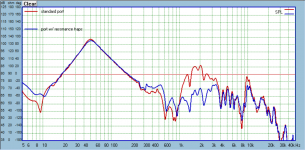
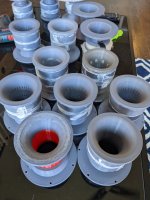
tmuikku> Thank you for the links. I've been working on designing ports that damp resonances for the last 2 years. I've got it pretty nailed, but I'd like to try the curved one you linked to, and maybe angled ends on a straight port. One thing I would recommend to anyone doing this sort of thing is to compare the harmonic distortion and spectrum plots versus an ordinary port. All of these attempts degrade performance. I suppose that should be expected. All fo my current efforts are focused on improving this non-linear performance. I also tried a normal port with the dacron batting used in MLTL, placed at the 1/2 and 1/4 wavelength positions and the results were minor resonance damping with much worse port SPL. So I don't think anything that damps in that way will work well. Below is my current best performer and a pic of some of some of the many tap designs I've tried. A few things I've learned: use a closed resonance trap, if you leave them open to the inside of the box, with just the damping material wrapped around the port, damping will be similar but distortion performance will be worse. The length of the port along the axis is very important, should be about 10% of port length. Place taps at both 1/2 and 1/4 wavelength along the port. The two together perform much better than either one alone.
Attachments
FYI/FWIW, drivers, vents should be at an odd harmonic for best overall performance and IME a box of uniform particle density at 'L'*0.42, same as was used for the original BR patent.
Last edited:
The design I plan to build is the Troels Gravesen SBA 16 MTM, which would suit by room size and waf.You plan to have the speakers placed at the wall, this will do really bad things to the sound, and you are concerned to a hypothetically midrange leakage of a front port? What is the design you plan to build, and how loud are you driving it?
Ralf
tmuikku> Thank you for the links. I've been working on designing ports that damp resonances for the last 2 years. I've got it pretty nailed, but I'd like to try the curved one you linked to, and maybe angled ends on a straight port. One thing I would recommend to anyone doing this sort of thing is to compare the harmonic distortion and spectrum plots versus an ordinary port. All of these attempts degrade performance. I suppose that should be expected. All fo my current efforts are focused on improving this non-linear performance. I also tried a normal port with the dacron batting used in MLTL, placed at the 1/2 and 1/4 wavelength positions and the results were minor resonance damping with much worse port SPL. So I don't think anything that damps in that way will work well. Below is my current best performer and a pic of some of some of the many tap designs I've tried. A few things I've learned: use a closed resonance trap, if you leave them open to the inside of the box, with just the damping material wrapped around the port, damping will be similar but distortion performance will be worse. The length of the port along the axis is very important, should be about 10% of port length. Place taps at both 1/2 and 1/4 wavelength along the port. The two together perform much better than either one alone.
Your work is quite extensive, thank you for sharing it to all!
That is very good performance on the mid "noise", what, +30db below the Helmholz resonance? nice!
Very good stuff for many projects, for those who want or need to go extra mile. Very high tech which comes handy when every bit of performance needs to be taken from small size for example.
I'm sticking with simple closed or open structure for short wavelengths and leave ports for subs for now on. These problems are nicely circumvent when the box, woofer, port all are acoustically small so that possible issues just disappear, only schuffing and compression is left. Perhaps closed subs as well, enough juice for home use, and no problems with simplest construct and lowest tech 🙂
Just had a gander at that design on Troels's site & I note that he states of that design 'You can place the port to the front or to the rear to your liking' so presumably he's either tried it, or is satisfied that the box response so-configured is acceptable. The balance in the FR looks like it's probably aimed at use further out from boundaries, but you may be able to tweak the tweeter level a bit if necessary without affecting the transfer functions too much by adjusting R1 & R6.The design I plan to build is the Troels Gravesen SBA 16 MTM, which would suit by room size and waf.
in his description and room gain calculation troels defines a distance of 100 cm to the back wall:SBA 16 MTM, which would suit by room size and waf

having it just 2 inches from back wall will heavily influence the tonal balance.
compare it with my simulation in post 21:
EDIT: just realized Scottmoose was quicker!
Yes but when I asked Troels about port placement he said bottom outlet was best as front outlet can give midrange leakage.Just had a gander at that design on Troels's site & I note that he states of that design 'You can place the port to the front or to the rear to your liking' so presumably he's either tried it, or is satisfied that the box response so-configured is acceptable. The balance in the FR looks like it's probably aimed at use further out from boundaries, but you may be able to tweak the tweeter level a bit if necessary without affecting the transfer functions too much by adjusting R1 & R6.
- Home
- Loudspeakers
- Multi-Way
- Port Placement