Hmm, I think the underutilization is relative because it depends on what one wants from the driver-box combination. If one wants lower going bass, then larger box (with lower tuning) have the advantage, but above the port tuning, the excursion would be higher (becasue of the lower port tuning) for the same SPL.4) Underutilisation of the driver.
But if we don't want the deepest bass then a smaller (hence lighter) box with higher tuning would enough if the driver have enough electrical power handling. So this would be the most bang for the buck or optimal driver utilization in the smallest possible box (aka max SPL from the given box size but with limited bass extension)?
BTW logic says that a larger box leads also to less power compression, and higher tuning still can be used with it, so if we use proper DSP and the box is rigid enough, then the only disadvantage I see is simply the physical size and weight of a larger box. But maybe there would less utilization of the driver's electrical power handling but this is not bad IMO, because of the lower power compression.
Last edited:

Indeed. Don't tell ME though! I am underutilising my drivers like mad. 🤭
Also there is this claim touching the underutilisation thingie, that such driver goes to horn, not a ported design, in order to be utilised. But I am not the one making such claims, so don't come at me for it. Just listing what I'm encountering.
Also there is this claim touching the underutilisation thingie, that such driver goes to horn, not a ported design, in order to be utilised. But I am not the one making such claims, so don't come at me for it. Just listing what I'm encountering.
I don't want to get on you. 😉 I'm just trying to figure out the reasons and the possible truths about claims.
Last edited:
No, you can. I just jokingly pointed out that you might be giving me SH for what OTHER people are saying, and I have none to do with it. All is cool.
There is some output, and port noises almost always mean losses. But that is an interesting idea to entertain.
At the moment it is developed to not have port noises and significant loss. That means that even at cutoff, it is somewhat efficient and doesn't unload. That means I can experiment with more loading to the port capabilities, to get lower F3, and secure it with a limiter. Or only 12db/oct highpass could be used, so some grunt of 25Hz still comes out of the sub. I experienced that once there is at least SOME SPL at low bass, it can be very noticable and enjoyable, but no need to go full power at 25Hz to a point of steering the whole system behind it (size and such).
At the moment it is developed to not have port noises and significant loss. That means that even at cutoff, it is somewhat efficient and doesn't unload. That means I can experiment with more loading to the port capabilities, to get lower F3, and secure it with a limiter. Or only 12db/oct highpass could be used, so some grunt of 25Hz still comes out of the sub. I experienced that once there is at least SOME SPL at low bass, it can be very noticable and enjoyable, but no need to go full power at 25Hz to a point of steering the whole system behind it (size and such).
Speaking of ports, is half Sd port area enough for say 18TBW100 tuned to ~30Hz? Simulator says at full tilt port air velocity tops about 12m/s but this doesn't tell anything about compression for example. I could do some end flares 3D printed, but it would be just easiest to use straight edge and utilize the port(s) as enclosure bracing at the same time.
Flared at 12m/s is in the ballpark of very reasonable. Ports have quite some losses, so one should strive for even more if possible.
You can go overboard and use some straight parts while adding some flares to the end. It can be made of wood still, no need for round flare. Just expanding one.
You can go overboard and use some straight parts while adding some flares to the end. It can be made of wood still, no need for round flare. Just expanding one.
I made some more sims on my use case, and to me it seems to me the unconventional undertuned design wins.
The case is this: compact ported 18" box zhat goes about flat to 40Hz, 35Hz -3dB, and then whatever downhill.
I simmed 96l box with RCF LF18X451.
Following graph is after EQ for the desired outcome.

Top row is 39Hz tuning, bottom is 30Hz tuning.
Same port volume in the box, power compression taken into account as best as possible*.
What might not be taken into account is port losses. The 39Hz one looks like it has higher flow, hence higher losses, which might not be reflected in the graph. But it might as well not be true, because port length can add losses on the 30Hz design. There is overall less cone displacement on the 39Hz design, so possibly even worse cooling and more thermal compression. It depends on how it's used.
All in all, the 30Hz design appears to win in the sim, and while I had some real world experience, I am sure it will hold its own to the higher tuned design. It is within 1dB.
Basically only real world measurements of this case need to be measured at this time. It will take time before I fully develop and build these.
The case is this: compact ported 18" box zhat goes about flat to 40Hz, 35Hz -3dB, and then whatever downhill.
I simmed 96l box with RCF LF18X451.
Following graph is after EQ for the desired outcome.
Top row is 39Hz tuning, bottom is 30Hz tuning.
Same port volume in the box, power compression taken into account as best as possible*.
What might not be taken into account is port losses. The 39Hz one looks like it has higher flow, hence higher losses, which might not be reflected in the graph. But it might as well not be true, because port length can add losses on the 30Hz design. There is overall less cone displacement on the 39Hz design, so possibly even worse cooling and more thermal compression. It depends on how it's used.
All in all, the 30Hz design appears to win in the sim, and while I had some real world experience, I am sure it will hold its own to the higher tuned design. It is within 1dB.
Basically only real world measurements of this case need to be measured at this time. It will take time before I fully develop and build these.
Thanks!Flared at 12m/s is in the ballpark of very reasonable. Ports have quite some losses, so one should strive for even more if possible.
You can go overboard and use some straight parts while adding some flares to the end. It can be made of wood still, no need for round flare. Just expanding one.
I'm asking as I'm hoping to get away with simplified system, port and support structure in one.
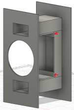
Here is quick sketch what I'm thinkin, ports acts as support between front and back panel. Port opening inside the box is toward the center of the box, from side of the port. I have no idea if this is good or bad idea, what you guys think?
Since I cannot predict what the end correction and tuning and stuff ends up with structure like this, the idea is to have the port wall that faces toward driver cutout detachable so I can tune it's length to change tuning after measuring the thing. On this quick sketch drew the detachable panel between the port side walls, should have "on top" of port sidewalls so it's easy to screw on / off and modify the length. Anyway, perhaps the idea is understandable? Box sides and other panel supports not rendered so that there is clear view to the ports.

I think it can work well.what you guys think?
If the port length resonance is within the speaker passband maybe turn the port openings away from the driver and put some stuffing material opposite from the internal port openings.
Also make sure to make "anti-turbulence"-roundovers at all high air velocity edges (marked in green, sorry for rough sketch!):

Also note that absolute airspeed is not that relevant (as long as it stays below absolute limit of 20-30 m/s), but the max air displacement in relation to the port radius (strouhal number) is.
For rectangular ports you can just take the port exit surface and take the radius of a corresponding circle.
Radius/displacement should remain above roughly 1,5 for a low compression, low turbulence system.
Hornresp can now plot the strouhal number graph, by the way!
Last edited:
@tmuikku
Yes. I do understand yu have to make many compromises on the design, so this is not one sided criticism. But these ports are not the most efficient way.
Two ports have more losses, eat up more material if one of the walls is not the same as box outer wall, flaring is problematic to make in this design.
So in the realm of run for efficiencies and power density, I find this design rather unfortunate.
Still can work lovely, without issue though.
Thanks stv!
This is 18" and strictly for sub duty. The box is roughly 220-240 litre after subtracting volume taken by ports and driver and supports. Each port area roughly 360cm2 so about 10.7cm equivalent circle radius. By displacement do you mean p-p xmax? Thats 2.4cm so strouhal number would be ~4 for one port. Two ports 720cm2 total so roughly 15cm equivalent circle radius and that makes strouhal number of ~6? I'll check it with hornresp later. Currently running vituixcad.
If my calculation are correct, then I could shrink the ports a bit? These get quite long with this much area, and strongly dependent on end correction value used in the simulator. I think smaller port area would give me less surprise with the tuning, and if ~12m/s and strouhal number of 4-6 were fine I think I should shrink it a bit.
Last edited:
Yes this is part of system for friends big house, so the outer dimensions are more important as aesthetic thing with rest of the system, than power density as I understand it (max output vs. easy to handle for gigs and per cost). I'm also limited by budget and all sorts of things, and it's not easiest application as I'll try and make system for hifi and party.@tmuikku
Yes. I do understand yu have to make many compromises on the design, so this is not one sided criticism. But these ports are not the most efficient way.
Two ports have more losses, eat up more material if one of the walls is not the same as box outer wall, flaring is problematic to make in this design.
So in the realm of run for efficiencies and power density, I find this design rather unfortunate.
Still can work lovely, without issue though.
The system will do double duty and tuned for both with DSP: low power hifi for most of the year, and another setting for occasional party. Hence two (or four) ports so I can block one or more to get tuning to ~20Hz for low power hifi, and +30Hz for party with bit more output.
I could make ports with walls but these are tough to adjust after measurement, I'm it afraid I get it wrong from start and would like to make sure there is possibility to adjust it after measuring without building the whole thing. I could leave one side open and so on of course. I'll likely buy 18TBX100 for it, as it's cheapest from bunch of woofers that simulate quite similarly, like the LF18X451.
No, I mean the (one way peak) air displacement in the port.By displacement do you mean p-p xmax?
You can calculate it and the strouhal number as I described here (with help from david mcbean):
https://www.diyaudio.com/community/...rbers-and-port-geometries.388264/post-7697685
Or you just use the dedicated graph in hornresp!
Also, I would always make ports as big as possible, unless
- you have space restrictions
- the port length resonance gets near the used bandwidth
- the enclosure resonances escaping through the (big) port will be a problem.
Last edited:
Cool cool, just above st 1.5 with max power and single 700cm2 port. I couldn't find high pass filter in a hurry though, so St would be likely bit higher with these settings. I think hornresp has no possibility for two ports? It's in the ballpark I think. Thanks for the tips, these help me finetune!

Since this is my first "high power" kinda box, I just need to build it and make next one better 😀 For example, chose center driver location and port locations trying to minimize the port leakage, but perhaps that is not much of a concern compared to the port compression and that kind of stuff. It is good point to utilize box walls for port to reduce pieces to cut for example, all of it is quite much work and costs money. But, we'll see how it works 😀 It's bit more than 100e for plywood and hobby time doesn't count as cost so not too bad loss if one prototype has to be burned.
ps. half Sd port with box Fs = Fb tuning St dips bit under 1.5
Last edited:
Yeah seems good, other than complexity and extra wood. Offset driver and port model in hornresp shows fine. There is also possibility to add elongations to the port, including some rounding. Could do some kind of rounding on the baffle side as well, perhaps 3D printed roundovers as I don't have large router bit to do it. But, what do you think, is it just no-no to have no round over? I could try something else completely, but this is the familiar approach so first in mind.
Here what hornresp shows

Attempt is to avoid this 😀

But, is this irrelevant as it's a sub after all? Should I rather prioritize the round overs and make layout which is easier to manufacture port rounding for? Correct answer would be, build one of each 😀
Here what hornresp shows
Attempt is to avoid this 😀
But, is this irrelevant as it's a sub after all? Should I rather prioritize the round overs and make layout which is easier to manufacture port rounding for? Correct answer would be, build one of each 😀
Attachments
Short answer: yes, it's a no-no!is it just no-no to have no round over?
Longer answer: it's worst to have sharp protruding tubes, thus the interior end is usually the one that needs most attention.
You could avoid most negative aspects of sharp edges (chuffing noise with port length resonant oscillation) by increasing the entrance/exit surfaces of the port as much as possible and by doing so reduce the airspeed.
Sharp edge effect, measured (round cardboard tube):
https://www.diyaudio.com/community/...rbers-and-port-geometries.388264/post-7503431
Same port, slow motion video capture:
https://www.diyaudio.com/community/...rbers-and-port-geometries.388264/post-7589749
(Apologies: the strouhal numbers are not correct in the video- need to be doubled for correct value!)
And have a look at post #407 on the next page for a video of a better shaped port end.
finally a post with flange variants including sound and chuffing noise spectra:
https://www.diyaudio.com/community/...rbers-and-port-geometries.388264/post-7594556
I really appreaciate, your info on ports is extensive and is already available, thanks for the links! Turbulence as source for other noises seems valid argument and shows why the flares should always be there. I need to factor them in.
Any rules of thumbs for how much velocity needs to be dropped, in other words what sized flare starts to be effective? Problem with port flared on both ends is that it needs to be adjusted from the middle if tuning is way off. How to make sure tuning is close enough? Thanks a ton!
Any rules of thumbs for how much velocity needs to be dropped, in other words what sized flare starts to be effective? Problem with port flared on both ends is that it needs to be adjusted from the middle if tuning is way off. How to make sure tuning is close enough? Thanks a ton!
Yeah going through your thread and reading the harman paper I'm in view that there is no universally good port but one for low SPL and another for high SPL, NFR 0.5 being the compromise between the two. And that there should be at least 12mm radius flare if nothing else 😀 Flange at inner end. I'll try your NFR calculator sheet and try to come up with something. Thanks for your continuing effort on the subject!
- Home
- Loudspeakers
- Subwoofers
- Port assisted subwoofer (PA)