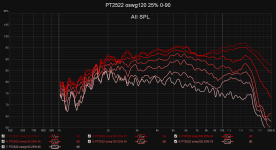
Some more data!
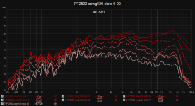
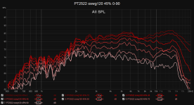
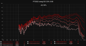
Ignore that some measurements start at 1 khz and are at 10 dB higher. I had some background noise when measuring so I bumped the amplitude to counterract.
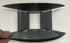
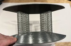
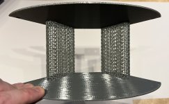
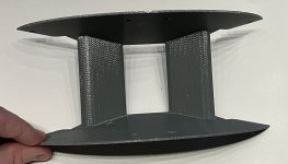
I wanted to find out which setup is better: slots at the edges or an actual porous waveguide! I made the porosity by printing with gyroid infill without any walls or top / bottom. the % is the infill percent. I used a 0.6mm nozzle when printing.
I believe the 2 notches between 2-3 khz are because of the vertical waveguide since it is also present on the measurement with only the mid flange. These notches should disappear when I connect multiple drivers in the CBT array and not just a single one.
Interesting that infill 25% and 45% measures almost identically.
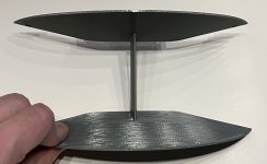
Turns out it works, but slots are better so that is probably what I will use.
Ignore that some measurements start at 1 khz and are at 10 dB higher. I had some background noise when measuring so I bumped the amplitude to counterract.
I wanted to find out which setup is better: slots at the edges or an actual porous waveguide! I made the porosity by printing with gyroid infill without any walls or top / bottom. the % is the infill percent. I used a 0.6mm nozzle when printing.
I believe the 2 notches between 2-3 khz are because of the vertical waveguide since it is also present on the measurement with only the mid flange. These notches should disappear when I connect multiple drivers in the CBT array and not just a single one.
Interesting that infill 25% and 45% measures almost identically.
Turns out it works, but slots are better so that is probably what I will use.
Attachments
-
 pt2522_wg_slots.jpg506.8 KB · Views: 108
 -
 PT2522 oswg120 slots 0-90.png65.7 KB · Views: 105
 -
 PT2522 oswg120 solid 0-90.png67.1 KB · Views: 101
 -
 PT2522 oswg120 45% 0-90.png67.5 KB · Views: 110
 -
 PT2522 oswg120 33% 0-90.png55.9 KB · Views: 111
 -
 PT2522 oswg120 25% 0-90.png55.6 KB · Views: 106
 -
 PT2522 oswg120 midFlare 0-90.png54.7 KB · Views: 108
 -
 pt2522_wg_25%.jpg388.9 KB · Views: 107
 -
 pt2522_wg_33%.jpg353.4 KB · Views: 108
 -
 pt2522_wg_45%.jpg411.6 KB · Views: 96
 -
 pt2522_wg_midFlange.jpg459.9 KB · Views: 99
 -
 pt2522_wg_solid.jpg519.7 KB · Views: 107
Last edited:

Where can I get the stl for this waveguide? I've designed my own waveguides for the PT2522 but with much less data and measurements I'd be happy to leverage your design!
Yes and no. I do have some of the stl files still on my disk but on top of that all waveguides are all generated with parametric CAD, and I have all the code saved in a versioned repository so if needed I can fetch the code used for any specific waveguide.

Here are the ones I have saved in a 3mf format that can be exported to stl. All have the vertical waveguide. If desired I should be able to generate waveguides without the vertical wg.
https://drive.google.com/file/d/1uc5YkzhcOqfLAXPHo2flqDKzgPjgEoX-/view?usp=sharing should give you access to the above mentioned 3mf which contains most of the waveguides.
If you want a configuration not in the file then I should be able to re-render the desired waveguide by loading the appropriate version of the code.
Phenomenal and thank you so much!! I will print and compare these to my present wg's this weekend. Which version did you find the most effective in your repo?
Phenomenal and thank you so much!! I will print and compare these to my present wg's this weekend. Which version did you find the most effective in your repo?
For my use case, which is minimal baffle, the best compromise was a small 90 degree oswg with slots open on the front and mini roundings + a mid flare on the rear:
https://www.diyaudio.com/community/threads/porous-dipole-waveguide-experiments.402258/post-7447415
https://www.diyaudio.com/community/threads/porous-dipole-waveguide-experiments.402258/post-7447420
If you use wider baffles then the answer is probably the wider baffle the better. I have had great results with 20-30 cm wide 90 degree OSWG variants. Performed amazing at 1400 hz and above but it was difficult for me to get the midrange drivers to play high enough. My plan was to hide the midranges inside the waveguides which worked great up to 600 hz but poorly above so no usable transition region so I discarded that idea and started toying around with minimal baffles to make the integration easier.
Although since then I have abandoned / paused that idea too. My current plan is to DIY my own planar driver so I can have a single driver that can be driven full range from 400 hz and upwards while still being close enough to the PT2522 in performance on the top end.
I actually also go for minimal baffle. I have a cad designed double walled teardrop enclosure (much like the B&W teardrop) that I fill with sand for my midrange enclosure. The back has a port that is threaded, I can fill it with a solid 3d printed screw to make it sealed, I have one that is a screw that is hollow end to end, and I have an aperiodic screw that is stuffed. The teardrop enclosure has a hole in the top that has threads so basically any tweeter or tweeter waveguide gets modified in CAD to add the proper 'screw size' so that it can be mounted on top so I will follow your lead and go for the 90 degree oswg with slots open as recommended then I will modify it in cad to add my 'screw in adapter' to make it modular.
My speakers are fully active and the crossover has been implemented/generated using audiolense and audiolense convolver. Everyone has their rabbit holes...DIY is too much fun.
Do you have a thread on your DIY planar driver out there so I can follow your progress?
My speakers are fully active and the crossover has been implemented/generated using audiolense and audiolense convolver. Everyone has their rabbit holes...DIY is too much fun.
Do you have a thread on your DIY planar driver out there so I can follow your progress?
Attachments

These look amazing...is that rebar being employed on the frame above the wooden portions?
Thank you for sharing all your efforts. Interesting and much appreciated! I've been doing quite some mental rumination on how to improve response from this PT2522 and PT6816 in dipole config. Until now I kinda just hammered the response with DSP but that kills a lot of efficiency and does not feel right. This build is now about to get a rebuild with new Seas lower mid bass, some minimal baffle of sorts, and I want to figure out a better way to smooth those planars. I might do some testing as @Patrick Bateman did with sealing up radiating points in a random pattern. I've also thought about ditching the 2522 altogether and just run with the 6816 as high as it goes.
View attachment 1213300
Do you have a thread on your DIY planar driver out there so I can follow your progress?
That I do! https://www.diyaudio.com/community/...d-in-a-dipole-cbt.412132/page-10#post-7776673
The main limiting factor for me is that I am building a CBT shaded dipole line array so the trick you are using where you place the tweeter above the midrange does not work for me.
Your speakers look to be monopoles? If so then large baffles are definently the way to go since it will let you match the off axis response to the midrange. The minimal baffles are most useful if you build a dipole.
They are monopoles but in some configurations the tweeter is a dipole. Thanks for the advice and logic I'll take it at this point! So please verify, if I want to go fully modular when I'm running the PT2522 open back I should go with the recommended waveguides, if I'm going with the PT2522 in a closed back configuration which files are the 'large baffles'? I'll tune in and watch your thread right now.
I'm trying to go back through the thread to determine which one you recommend from the wide baffle group but there's so much data here that I'm having trouble determining which one to run with. Can you give me the specific number in the 1-28 schema you have the project file that you're recommending?
None of the waveguides in the file are large baffles. With a large baffle I mean what you have in the image you posted. A waveguide width as wide as the midrange you will cross from which will let you have a nice overlapping crossover region.They are monopoles but in some configurations the tweeter is a dipole. Thanks for the advice and logic I'll take it at this point! So please verify, if I want to go fully modular when I'm running the PT2522 open back I should go with the recommended waveguides, if I'm going with the PT2522 in a closed back configuration which files are the 'large baffles'? I'll tune in and watch your thread right now.
All of the ones in the files are small waveguides compared to normal. In short, the throat width of the waveguide determines from what frequency you can control the dispersion. A large waveguide controls from a lower frequency than a smaller one.
Normally the point of the waveguide is to match the control and match the off axis response of the tweeter to the midrange, hence usually similar throat width to the mid width.
In my dipole waveguides, that is not the goal. The goal was rather to control the dispersion in the dipole peak region where the rear driver influences the front driver and causes a null. The dipole peak is only a problem when used as a dipole, and is just slightly below 7 khz. This is why my wavegudes are so small. And usually the solution is to go with bigger waveguides, which in monopole is fine because you use lots of tricks that aren't available in a dipole. One option is to split the mid into multiple smaller drivers and do a synergy horn setup. That works great in a monopole but doesn't work in a dipole. Same with time alignment, in a dipole the drivers have to be centered but in a monopole setup they don't.
My midrange driver is a 6" in this configuration or perhaps a 6.5, I should choose a waveguide that isa proximately the same width?
Have you built a synergy horn or heard one? I've seen the designs and have read up on them but have not had any real exposure.
Have you built a synergy horn or heard one? I've seen the designs and have read up on them but have not had any real exposure.
My midrange driver is a 6" in this configuration or perhaps a 6.5, I should choose a waveguide that isa proximately the same width?
Same width is a good idea yes. Then the midrange will start to loose off axis response at the same time the waveguide controls it which will give you a nice overlapping region where you can cross with matching off axis response.
Have you built a synergy horn or heard one? I've seen the designs and have read up on them but have not had any real exposure.
No, only my dipole inspired variant which isn't really a horn:


The midranges are 3.5" ND91 and the tweeters are PT2522s.
Inspired by the idea of a synergy horn by placing the midranges around the tweeters and letting the merge into each other by having the slots. The slots also help reducing the dipole peak since it allows some pass through.
Woofers response:

Tweeters response:

In this dipole setup it doesn't work because the tweeter doesn't play low enough. If the tweeters could be crossed at 400-600 hz then it would work great but the PT2522 can't.
In a monopole setup you can do tricks, however, to increase how high the woofers can play. You can shift the woofers into the waveguide side. In a synergy they usually have elongated slots or round holes to let the midrange sound through while still acting as a mostly flat surface to the tweeter. You could also use infill like I played around with in https://www.diyaudio.com/community/threads/porous-dipole-waveguide-experiments.402258/post-7480408 instead of slots or holes. And since the ctc distances can be made way shorter for the monopole setup this allows for a far higher crossover frequency.

Thanks! And sorry for late reply, for some reason I was logged out and have not gotten any notifications.These look amazing...is that rebar being employed on the frame above the wooden portions?
I'm not entirely sure I understand your question, but I can send more pictures if you want. Maybe keep OT to a minimum 😉
At the moment these speakers are partly dismantled and after a good deal of measuring and experimenting I'm not satisfied with these planar drivers, so I have given up(for now). Plan is to make a new top end more inspired of the LX521
- Home
- Loudspeakers
- Multi-Way
- Porous dipole waveguide experiments