I just got another crazy Idea I want to try (next monday):
So far all my experiments have been front-back symmetric. What If I change that? Say if I put the minimal rounding and a modest middle edge on the front but a shallow waveguide on the rear. The theory would be that the rear wg would control the response around the 7 khz dip and thus mitigate / reduce it on the front. Would it actually work like that? No idea but I want to find out 🙂
Symmetry is nice and all but as far up as 7 khz I'm perfectly willing to compromise the rear response somewhat in exchange of improving the front response.

More data!
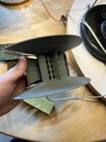
I printed another combo, the mini roundovers and the mid flange but no extra roundovers in between. Then of course some combinations of asymmetric setups.
The first measurement is the mini roundover reference I've used again.
Then the roundover and flare without the middle roundings. Looks to be the best symmetric setup so far.
Then the asymmetric setups are in the following order:
1. front: mini roundover with flare, rear: shallow waveguide with 2 edge slots.
2. front: shallow waveguide (~ 120 degree) with 2 edge slots, rear: mini roundover with flare.
3. front: original waveguide (~ 90 regree) with 2 edge slots, rear: mini roundover with flare.
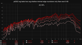
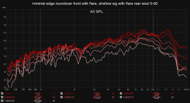
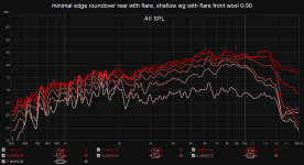
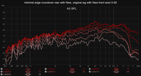
And some initial conclusions is that using a waveguide improves the response somewhat on the side of the waveguide, so using a wg on the rear to clean up the front didn't work. But it does indeed reduce the 7 khz dip by a significant amount. The best currently of the asymmetric is probably the steeper original waveguide where the dip is eliminated enough that I could EQ out the little bump below without having to be heavy handed. It introduces some problems but those problems are higher up in frequency and even then it isn't that bad. So I will probably adjust the front waveguide some more and see what works best.
But the mini roundover and only mid flange does measure pretty good by itself. There is the 7 khz dip but it is uniform off axis so I could probably get away with a EQ boost. But I don't want to get heavy handed with EQ so I would prefer to use acoustic solutions like a waveguide to solve the problem.
I printed another combo, the mini roundovers and the mid flange but no extra roundovers in between. Then of course some combinations of asymmetric setups.
The first measurement is the mini roundover reference I've used again.
Then the roundover and flare without the middle roundings. Looks to be the best symmetric setup so far.
Then the asymmetric setups are in the following order:
1. front: mini roundover with flare, rear: shallow waveguide with 2 edge slots.
2. front: shallow waveguide (~ 120 degree) with 2 edge slots, rear: mini roundover with flare.
3. front: original waveguide (~ 90 regree) with 2 edge slots, rear: mini roundover with flare.
And some initial conclusions is that using a waveguide improves the response somewhat on the side of the waveguide, so using a wg on the rear to clean up the front didn't work. But it does indeed reduce the 7 khz dip by a significant amount. The best currently of the asymmetric is probably the steeper original waveguide where the dip is eliminated enough that I could EQ out the little bump below without having to be heavy handed. It introduces some problems but those problems are higher up in frequency and even then it isn't that bad. So I will probably adjust the front waveguide some more and see what works best.
But the mini roundover and only mid flange does measure pretty good by itself. There is the 7 khz dip but it is uniform off axis so I could probably get away with a EQ boost. But I don't want to get heavy handed with EQ so I would prefer to use acoustic solutions like a waveguide to solve the problem.
Attachments
-
 roundover-flange-no-mini-roundings.JPG439.8 KB · Views: 104
 -
 mini-front-shallow-back.JPG450.6 KB · Views: 111
 -
 pt2522 wg tests horz wg shallow minmal edge roundover 3 0-90.png60.5 KB · Views: 101
 -
 pt2522 wg tests horz wg shallow minmal edge roundover only flare wool 0-90.png61.3 KB · Views: 86
 -
 minimal edge roundover front with flare, shallow wg with flare rear wool 0-90.png60.6 KB · Views: 88
 -
 minimal edge roundover rear with flare, shallow wg with flare front wool 0-90.png61.7 KB · Views: 79
 -
 minimal edge roundover rear with flare, original wg with flare front wool 0-90.png62.4 KB · Views: 87
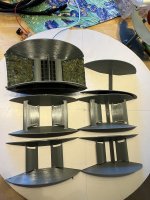
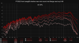
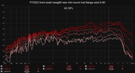
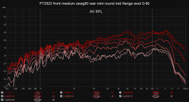
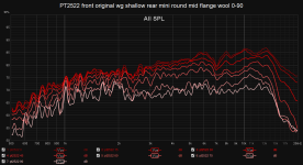
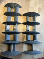
All the following measurements are with wool sheets like in the top left one. The rear on all are mini roundings with flare.
1. top left: minimal roundings and mid flare
2. top right: just mid flare
3. mid left: mid-size oswg with 90 degree throat and 0.75cm throat roundover, 1cm edge roundover.
4. mid right: same as left but with mid flare.
5. bot left: mid: small oswg with 90 degree throat and 0.75cm throat roundover, 1cm edge roundover.
6. bot right: same as left but with mid flare.
I found that with smaller waveguides I get the best response if I only have a waveguide on the front and on the back just have a mid flare like the top right.
The measurements are in the following order:
1
3
4
5
6
My conclusion from this is that with a real waveguide on the front I get the best performance without the mid flare. If I just have minimal roundings or nothing at all on the sides, then the mid flare does help.
Attachments
-
 IMG_0389.JPG580.5 KB · Views: 111
 -
 PT2522 front mini round mid flare rear mini round mid flare wool 0-90.png64.3 KB · Views: 105
 -
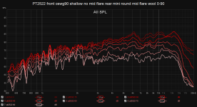 PT2522 front oswg90 shallow no mid flare rear mini round mid flare wool 0-90.png66.2 KB · Views: 87
 -
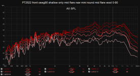 PT2522 front oswg90 shallow only mid flare rear mini round mid flare wool 0-90.png65.6 KB · Views: 81
 -
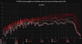 PT2522 front oswg90 no mid flare rear mini round mid flare wool 0-90.png64.9 KB · Views: 81
 -
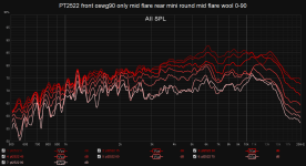 PT2522 front oswg90 only mid flare rear mini round mid flare wool 0-90.png65.1 KB · Views: 111
I played around some more with adding some EQ to boost the 7 khz dip. With a narrow 7 khz 3 dB boost on a shallow oswg90 on the front and the mini roundings with mid flare on the rear I get:
Pretty decent performance. I still want to play around some more with 120 degree OSWG profiles. Ideally a slightly bigger one such that I don't have to add the EQ boost at 7 khz but if that fails then this result is still pretty good all things considered.
This was measured on a different day than the post before so the measurements are not equivalent. I also noticed that with an asymmetric setup where I only have a waveguide on the front this shifts the 90 degree null slightly forwards so the 75-90 degree responses are a bit jumpy on some on my measurements. This measurement, however, I dialed it it in centered to the waveguide.
Attachments
More data!
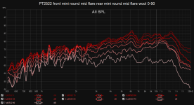
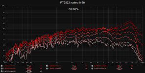
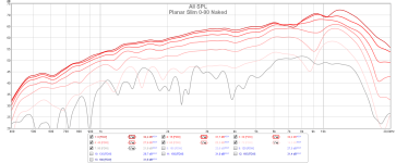
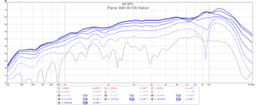
Conclusion: The small oswg90 with just mid flanges on the rear is the best. So pretty much what I measured in https://www.diyaudio.com/community/threads/porous-dipole-waveguide-experiments.402258/post-7447420
I will continue to experiment how to configure the slots for best performance for this specific shape.
All measurements are with X in the front and mini roundings mid flare on the rear except the small oswg90 with mid flange. A rear with only the mid flange performs slightly better than with mini roundings but the difference is very small.
Conclusion: The small oswg90 with just mid flanges on the rear is the best. So pretty much what I measured in https://www.diyaudio.com/community/threads/porous-dipole-waveguide-experiments.402258/post-7447420
I will continue to experiment how to configure the slots for best performance for this specific shape.
| original exponential wg with mid flange | |
| shallow exponential wg | small oswg90 with mid flange |
| medium oswg90 | small oswg90 |
| medium radial wg (3cm throat, 1.5cm edge) | small radial wg |
| mini roundings mid flare | only mid flare |
All measurements are with X in the front and mini roundings mid flare on the rear except the small oswg90 with mid flange. A rear with only the mid flange performs slightly better than with mini roundings but the difference is very small.
Attachments
-
 PT2522 front rear mini round mid flange naked 0-90 2023-09-11.png64.4 KB · Views: 94
 -
 PT2522 front small radial wg rear mini round mid flange wool 0-90.png65.9 KB · Views: 75
 -
 PT2522 front medium radial wg rear mini round mid flange wool 0-90.png66.5 KB · Views: 66
 -
 PT2522 front small oswg90 rear mini round mid flange wool 0-90.png64.1 KB · Views: 64
 -
 PT2522 front medium oswg90 rear mini round mid flange wool 0-90.png63.3 KB · Views: 70
 -
 PT2522 front small oswg90 mid flare rear mid flange wool 0-90.png63.3 KB · Views: 75
 -
 PT2522 front original wg shallow rear mini round mid flange wool 0-90.png65.4 KB · Views: 71
 -
 PT2522 front original wg only mid flare rear mini round mid flange wool 0-90.png63.9 KB · Views: 92
 -
 IMG_0393.JPG630 KB · Views: 100
A little off topic - I see your tweeters have the same 7k dip as mine - do you have any idea where this may come from? I thought mine was bad, but both measure the same way. It must be related to some dimension I think.
It's because GRS copied the Neo3 PDR which is the same. It is the classic dipole peak problem. I would have prefered them to copy the Neo3W instead which doesn't have this problem.A little off topic - I see your tweeters have the same 7k dip as mine - do you have any idea where this may come from? I thought mine was bad, but both measure the same way. It must be related to some dimension I think.
The driver has 3 rows of magnets and mainly radiates from the inner holes with a slight tapering from the outer holes. This improves off axis response on the top end but causes problems when used as a dipole since the effective radiating area is smaller. This causes the metal frame or baffle to be big relative to the radiating area which brings down the dipole peak. In this case down to 7 hkz which is what I'm trying to mitigate with different ideas.
Thank you for sharing all your efforts. Interesting and much appreciated! I've been doing quite some mental rumination on how to improve response from this PT2522 and PT6816 in dipole config. Until now I kinda just hammered the response with DSP but that kills a lot of efficiency and does not feel right. This build is now about to get a rebuild with new Seas lower mid bass, some minimal baffle of sorts, and I want to figure out a better way to smooth those planars. I might do some testing as @Patrick Bateman did with sealing up radiating points in a random pattern. I've also thought about ditching the 2522 altogether and just run with the 6816 as high as it goes.

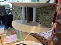
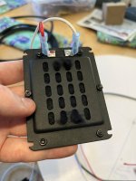
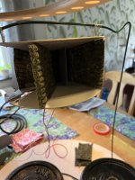
I got one of my ideas and wanted to try something. My thought process was: The PT2522 is a copy of the Neo3 PDR where because the inner holes radiate more than the outer we get the sharp dipole peak. So what happens if we dampen the inner holes?
I fetched some thick wool yarn and inserted it into the middle holes on both the front and the rear. The results are pretty awesome! It doesn't completely fix the null but it does reduce it from 5 dB to 2 dB and also broadens the null so it isn't as sharp anymore. Maybe I should try to add even more damping. Say a sheet of wool carpet in front of the mid holes too and see if it improves the response even more. I'll have to try it next weekend.
I fetched some thick wool yarn and inserted it into the middle holes on both the front and the rear. The results are pretty awesome! It doesn't completely fix the null but it does reduce it from 5 dB to 2 dB and also broadens the null so it isn't as sharp anymore. Maybe I should try to add even more damping. Say a sheet of wool carpet in front of the mid holes too and see if it improves the response even more. I'll have to try it next weekend.
Attachments
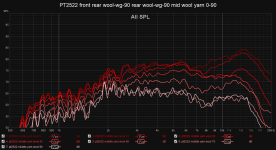
And now more data but with middle yarn holes.
First I tried tested a 90 degree symmetric wg with wool carpet sheets. The next is the 90 degree wool wg on the rear and a flat wool wg on the front.
The second is better but nothing to rave about.
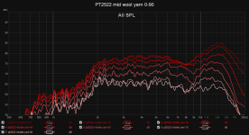
I went back to test with some more hard waveguides and they perform pretty well with the middle yarned holes. I added some slight EQ to smooth things out. No large boosts and Q=3 so no super sharp fixes.
The small 120 degree wg with mid yarned holes is probably the best one yet. I'll probably do some more tests and maybe do a 105-110 wg version and play around with the inner throat roundover and see if I can fix the 45 degree 9 khz dip. But if I can't then it's a sacrifice I'm happy to make since the 0-30 response is pretty much perfect.
First I tried tested a 90 degree symmetric wg with wool carpet sheets. The next is the 90 degree wool wg on the rear and a flat wool wg on the front.
The second is better but nothing to rave about.
I went back to test with some more hard waveguides and they perform pretty well with the middle yarned holes. I added some slight EQ to smooth things out. No large boosts and Q=3 so no super sharp fixes.
The small 120 degree wg with mid yarned holes is probably the best one yet. I'll probably do some more tests and maybe do a 105-110 wg version and play around with the inner throat roundover and see if I can fix the 45 degree 9 khz dip. But if I can't then it's a sacrifice I'm happy to make since the 0-30 response is pretty much perfect.
Attachments
-
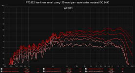 PT2522 front rear small oswg120 wool yarn wool sides modest EQ 0-90.png57.9 KB · Views: 113
 -
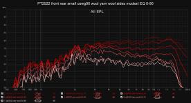 PT2522 front rear small oswg90 wool yarn wool sides modest EQ 0-90.png62.9 KB · Views: 94
 -
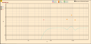 PT2522 front rear oswg120 mid yarn wool sides modes EQ.png29 KB · Views: 94
 -
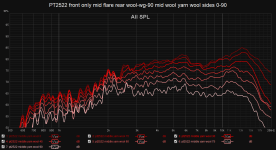 PT2522 front only mid flare rear wool-wg-90 mid wool yarn wool sides 0-90.png62.9 KB · Views: 89
 -
 PT2522 front rear wool-wg-90 rear wool-wg-90 mid wool yarn 0-90.png64.3 KB · Views: 114
 -
 IMG_0395.JPG385.4 KB · Views: 129
Very nice results indeed! Have you had a look at the distortion graphs after these mods? I'm no expert in measuring but these drivers seem to have some excessive distortion when left unmodified
Good work, nice idea 🙂
If you have some experience in CAD, you can speed up and simplify the printing of your guides by a huge amount. Split the bottom/top plates into separate flat printed plates, and print the vertical connecting elements separately. Add some locating holes where you can use something like IKEA bookshelf plugs or small dowels to connect the pieces, superglue them together. Now everything is a flat print, needs no supports, and do hopefully have better dimensional accuracy...
Have you tried the taller GR PT6816? I think it actually works better for the high end than the smaller NEO3 clone.... Less of a 7kHz dip, just a small bump at 13-14k to attenuate. Attenuation is alöways better for digital filters 🙂
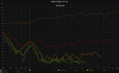
They do distort yes. Or at least a lot when the low end of the frequencies. Below 1.5 khz the PT2522 starts to distort a lot but above 1.5 khz it is pretty much pure 2nd harmonic so excellent performance. In a solo setup you'd probably want to cross far higher but I plan to use 17 of them in a curved CBT array so I can get away with a lower crossover.Very nice results indeed! Have you had a look at the distortion graphs after these mods? I'm no expert in measuring but these drivers seem to have some excessive distortion when left unmodified
But yeah, the wool yarn seems to affect the low end response so doing some more distortion measurements is probably a good idea.
If you have some experience in CAD, you can speed up and simplify the printing of your guides by a huge amount. Split the bottom/top plates into separate flat printed plates, and print the vertical connecting elements separately. Add some locating holes where you can use something like IKEA bookshelf plugs or small dowels to connect the pieces, superglue them together. Now everything is a flat print, needs no supports, and do hopefully have better dimensional accuracy...
I thought about it but I am lazy and my printer is fast enough that I didn't bother yet. But when I print for real I might do something like that. And dimentionally it is accurate enough.
I have. It works great for a straight array but I want to build a curved CBT array and the tall height of the PT6816 caused nulls and peaks that can be avoided by using a less tall tweeter like the PT2522.Have you tried the taller GR PT6816? I think it actually works better for the high end than the smaller NEO3 clone.... Less of a 7kHz dip, just a small bump at 13-14k to attenuate. Attenuation is alöways better for digital filters 🙂
Attachments
Sorry in advance to OP if thread hijacking, but my measurements of the PT6816-8 does not give quite the same result. Maybe some issue with dipole measuring distance?Have you tried the taller GR PT6816? I think it actually works better for the high end than the smaller NEO3 clone.... Less of a 7kHz dip, just a small bump at 13-14k to attenuate. Attenuation is alöways better for digital filters 🙂
I'll try to find my measurements in the archived folder later 🙂 Ask Oll too about his results too...
I had wiggles of around 1-2dB in the 8-10k region, but a generally flat overall trend. Mine was measured in a sectioned WG, with short vanes between the four slits, and heavy foam mounted directly to the backside (they were quasi-open baffle. If I remember correctly, my naked driver dipole measurements were so spiky all through the lower treble that I generally disregarded them as useless for further work without some sort of box or waveguide...
I had wiggles of around 1-2dB in the 8-10k region, but a generally flat overall trend. Mine was measured in a sectioned WG, with short vanes between the four slits, and heavy foam mounted directly to the backside (they were quasi-open baffle. If I remember correctly, my naked driver dipole measurements were so spiky all through the lower treble that I generally disregarded them as useless for further work without some sort of box or waveguide...
If you find the measurements that would be great, thanks. Off course @OllBoll, if you have your results handy. I know I've seen various measurements but hard to remember all the different threads.
I have full spin measurements horizontal and vertical of nude dipole PT2522 and PT6816 from 1 meter, if someone is interested. That one I posted is PT6816 on axis
I have full spin measurements horizontal and vertical of nude dipole PT2522 and PT6816 from 1 meter, if someone is interested. That one I posted is PT6816 on axis
I found off some old measurements of a PT6816.
I have also have measurements where I run yarn through the outer holes, doesn't fix the 7 khz dip. But I think the yarn on the inner holes fix should work on the PT6816 since it pretty much is a tall PT2522.
I have also have measurements where I run yarn through the outer holes, doesn't fix the 7 khz dip. But I think the yarn on the inner holes fix should work on the PT6816 since it pretty much is a tall PT2522.
Attachments
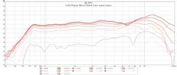
Thanks for posting measurements. What distance was that? Looks like my result has more severe 10k dip
at 0.5 - 1 m if I remember correctly, indoors and probably not with a perfect timing window so take the measurements with a grain of salt.What distance was that? Looks like my result has more severe 10k dip
Thankfully I received my 16 6816’s before they went out of stock. I’ll be doing vertical arrays of 8 per channel. For testing so far, I’m using just four in a vertical array hanging from a jig of 2x4’s out in the yard for measuring in between bird chirps and such. Good luck with your project…….after some critical listening I think I made a personal mistake…..i’m already missing point source radiation with only 32” of drivers compared to a 1.25” dome or CD.
- Home
- Loudspeakers
- Multi-Way
- Porous dipole waveguide experiments