Fully HW-based pop and click free relay attenuator.
All done with some clever use of digital logic and accurate timing.
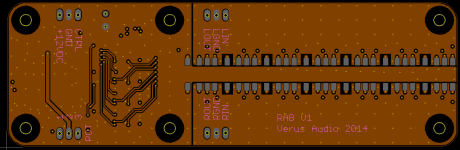
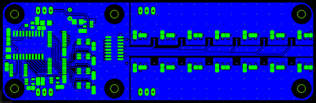
128 x 0.65dB steps for an attenuation range of 0 to -82dB.
High quality Omron G6K relays, high quality low noise, low distortion 0.1% Susumu RG Thin Film resistors.
Perfect channel balance, from max to min attenuation.
The attenuator needs a 10K termination resistor to maintain a 10K total attenuator impedance.
125mm x 40mm 4 Layer PCB.
EDIT : For those who want a PCB, the price is $20(PCB) + $3(Shipping) to all of Europe and the US.
Send me an E-mail with your DiyA username, real name and adress and I will send you a PayPal request.
I wont be able to send anything before Tuesday, April 22 due to easter holidays.
Furthermore, there will be an updated component placement file showing the exact placement and orientation of the components. Component number, placement and orientation is not shown on the silkscreen since I wanted a clean look so this is as intended.
The BOM is 100% accurate and everything should be in stock at Mouser. Although I would strongly urge people to order 1 extra 1uF, 0805 capacitor on top of the 9 needed for C5-C13. I will explain it later and the attenuator will work without it, although it could be a little "touchy" due to the potential for noise pickup from the potentiometer and long wires, the extra 1uF cap fixes it. EDIT : Explained in Post #17
The BOM is for the PCB mounted components ONLY, everything else needed, like 12 Volt DC power supply, Potentiometer, 3 pin molex housings and crimps, wires etc. is up the builder himself to decide upon and provide.
Have any questions, do not hesitate to ask. 🙂
All done with some clever use of digital logic and accurate timing.
128 x 0.65dB steps for an attenuation range of 0 to -82dB.
High quality Omron G6K relays, high quality low noise, low distortion 0.1% Susumu RG Thin Film resistors.
Perfect channel balance, from max to min attenuation.
The attenuator needs a 10K termination resistor to maintain a 10K total attenuator impedance.
125mm x 40mm 4 Layer PCB.
EDIT : For those who want a PCB, the price is $20(PCB) + $3(Shipping) to all of Europe and the US.
Send me an E-mail with your DiyA username, real name and adress and I will send you a PayPal request.
I wont be able to send anything before Tuesday, April 22 due to easter holidays.
Furthermore, there will be an updated component placement file showing the exact placement and orientation of the components. Component number, placement and orientation is not shown on the silkscreen since I wanted a clean look so this is as intended.
The BOM is 100% accurate and everything should be in stock at Mouser. Although I would strongly urge people to order 1 extra 1uF, 0805 capacitor on top of the 9 needed for C5-C13. I will explain it later and the attenuator will work without it, although it could be a little "touchy" due to the potential for noise pickup from the potentiometer and long wires, the extra 1uF cap fixes it. EDIT : Explained in Post #17
The BOM is for the PCB mounted components ONLY, everything else needed, like 12 Volt DC power supply, Potentiometer, 3 pin molex housings and crimps, wires etc. is up the builder himself to decide upon and provide.
Have any questions, do not hesitate to ask. 🙂
Attachments
Last edited:
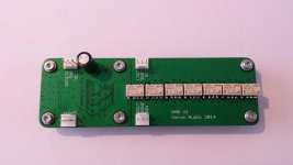
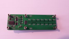
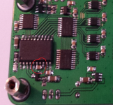
Sorry for the crappy pictures, I am not much of a photographer. 😀
The board has been assembled and tested.
It works just as expected, no pops or clicks in the audio when switching volume.*
*Apart from the very low noises when a relay is switched in at the top of a waveform, this is to be expected on ALL relay beased attenuators. This is due to the fact that there is way to do zero crossing detection when using relays. It is only detectable at very high volume levels.
Attachments
Last edited:
It works just as expected, no pops or clicks in the audio when switching volume.*
*Apart from the very low noises when a relay is switched in at the top of a waveform, this is to be expected on ALL relay beased attenuators. This is due to the fact that there is way to do zero crossing detection when using relays. It is only detectable at very high volume levels.
Sitting here and listening to some great music and playing around with the volume using this new attenuator, I can safely say that it is a non issue.
I might be deluding myself but it does seem to be improved over just an Alps RK27, one thing that is certain though, is that the channel balance is absolutely spot on all the way down to max attenuation.
Why do it in SW when a good old school HW design can do the same thing. 😀
Could not be happier. 😎
Last edited:
I have som PCBs left.
$20+shipping for a PCB.
Hi,
How many pub I need for 2 channel?
Too bad it uses surface-mount devices.
Surface mounted devices are the way of the future.
I could have made it with through hole components but it would end up a lot bigger. I needed something compact.
Hi,
How many pub I need for 2 channel?
You need 1 PCB for 2 Channels.
Those SMd part doesn't look that bad.
Some of the parts are really small, however with some skill and patience it can be done.
I did mine without using a microscope and then I used a small loupe to check for solder bridges.
Patience is the key.
I would like to buy one board. What is the supply voltage?
12 Volt DC.
Hi Neutrality,
One dumb question, how do you dial the volume on this attenuator module?
You just connect a 10-50k linear potentiometer to the molex header marked "pot" and then you just use it as a normal volume control.
The potentiometer puts out a voltage between 0(max attenuation) and 5V(Min attenuation. That voltage is read by an ADC that converts it to a binary value which is then used to control the relais.
So you not only get the smooth feeling of turning a normal potentiometer, like in a normal volume control, but you also get the very accurate channel matching from max to min attenuation, low noise, low distortion that you typically get from a relay attenuator.
Here is an updated RAB V1 - BOM - Mouser with the extra 1uF cap added.
Top component placement and orientation.
Bottom component placement and orientation.
Top component placement and orientation.
Bottom component placement and orientation.
Attachments
Last edited:
- Status
- Not open for further replies.
- Home
- Source & Line
- Analog Line Level
- Pop/click free HW-based relay attenuator