Re: Re: Re: PSMLS dedicated buffer - schematic
Hmm, I had Modwright modify this unit some 5 years ago now.
The DMM reads 600ohms out of RCA Out to RCA ground. I assume they are 600ohm output trannies from Sowter. Are they hooked up correctly in Denon 2900, I have no idea. I dont seem to be missing too much hooking it up to anything sounds good, of course, I probably can't hear well. Moving recently to solid state, I am not sure that it's optimal for this, probably not. I probably ordered to better fit old SE tube amps.
😀
Zen Mod said:
just a moment - you told that you have 600 ohms output xformers on your CD - but question is - are they already connected in a way that you have ~ 600 ohms output impedance ?
having them ON output is one thing ( as sometime used - as I/V conversion gadgets )
having them connected properly is another thing
give me more informations regarding that .
Hmm, I had Modwright modify this unit some 5 years ago now.
The DMM reads 600ohms out of RCA Out to RCA ground. I assume they are 600ohm output trannies from Sowter. Are they hooked up correctly in Denon 2900, I have no idea. I dont seem to be missing too much hooking it up to anything sounds good, of course, I probably can't hear well. Moving recently to solid state, I am not sure that it's optimal for this, probably not. I probably ordered to better fit old SE tube amps.
😀
600 or not .....
DMM reading 600 means nothing ;
ask them what they made - regarding output impedance ;
or - just measure that
if you don't know how ....... ask 😉
Tea-Bag said:
Hmm, I had Modwright modify this unit some 5 years ago now.
The DMM reads 600ohms out of RCA Out to RCA ground. I assume they are 600ohm output trannies from Sowter. Are they hooked up correctly in Denon 2900, I have no idea. I dont seem to be missing too much hooking it up to anything sounds good, of course, I probably can't hear well. Moving recently to solid state, I am not sure that it's optimal for this, probably not. I probably ordered to better fit old SE tube amps.
😀
DMM reading 600 means nothing ;
ask them what they made - regarding output impedance ;
or - just measure that
if you don't know how ....... ask 😉
Re: 600 or not .....
Well I assumed measuring there was true output impedence, even if other parts are after output trannie.
I can crack it open and measure the trannie output impendence,
assuming this is in fact meaningful.
I will need to get part # etc. to figure out trannie wiring Maybe I can get schematic of modded player. Wouldn't that be nice....🙂
Zen Mod said:
DMM reading 600 means nothing ;
ask them what they made - regarding output impedance ;
or - just measure that
if you don't know how ....... ask 😉
Well I assumed measuring there was true output impedence, even if other parts are after output trannie.
I can crack it open and measure the trannie output impendence,
assuming this is in fact meaningful.
I will need to get part # etc. to figure out trannie wiring Maybe I can get schematic of modded player. Wouldn't that be nice....🙂
Re: Re: 600 or not .....
measuring output impedance is easy ;
first you need CD with recorded steady sine wave sig with frequency between 400 and 1KHz
put it in CD player ; disconnect all signal cables from CD - so it isn't connected to any load
play that CD - and measure output voltage ( directly at output RCA ) ;
write it down .
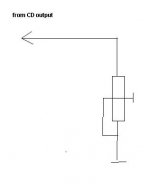
then take one pot - wire it as shown on sketch ;
pot can have 4k7 or 3k3 value
connect it qas shown - between hot and gnd on RCA CD output
play same track
measure output voltage with DMM as previously ( between RCA hot and gnd) , and decrease pot untill you have exactly 50% of previously measured voltage ;
power off
disconnect everything
measure with DMM what is resistance of pot in that position ;
that's output impedance of your superdoopertweaked CD
easy - isn't it ?
Tea-Bag said:
Well I assumed measuring there was true output impedence, even if other parts are after output trannie.
I can crack it open and measure the trannie output impendence,
assuming this is in fact meaningful.
I will need to get part # etc. to figure out trannie wiring Maybe I can get schematic of modded player. Wouldn't that be nice....🙂
measuring output impedance is easy ;
first you need CD with recorded steady sine wave sig with frequency between 400 and 1KHz
put it in CD player ; disconnect all signal cables from CD - so it isn't connected to any load
play that CD - and measure output voltage ( directly at output RCA ) ;
write it down .
then take one pot - wire it as shown on sketch ;
pot can have 4k7 or 3k3 value
connect it qas shown - between hot and gnd on RCA CD output
play same track
measure output voltage with DMM as previously ( between RCA hot and gnd) , and decrease pot untill you have exactly 50% of previously measured voltage ;
power off
disconnect everything
measure with DMM what is resistance of pot in that position ;
that's output impedance of your superdoopertweaked CD
easy - isn't it ?
Attachments
Re: Re: Re: 600 or not .....
That was interesting. 1K sine wave used.
830 ohms measured off of pot enabled RCA once removed from CDP.
So it's a highish output....
Mike
Zen Mod said:
measuring output impedance is easy ;
first you need CD with recorded steady sine wave sig with frequency between 400 and 1KHz
put it in CD player ; disconnect all signal cables from CD - so it isn't connected to any load
play that CD - and measure output voltage ( directly at output RCA ) ;
write it down .
then take one pot - wire it as shown on sketch ;
pot can have 4k7 or 3k3 value
connect it qas shown - between hot and gnd on RCA CD output
play same track
measure output voltage with DMM as previously ( between RCA hot and gnd) , and decrease pot untill you have exactly 50% of previously measured voltage ;
power off
disconnect everything
measure with DMM what is resistance of pot in that position ;
that's output impedance of your superdoopertweaked CD
easy - isn't it ?
That was interesting. 1K sine wave used.
830 ohms measured off of pot enabled RCA once removed from CDP.
So it's a highish output....
Mike
Attachments
Re: Re: Re: PSMLS dedicated buffer - schematic
ZM -
I find no reference elsewhere of Poor Serbian Buffer - does a schematic exist, or this part subbing in papa's design?
I assume buffer of some sort w.o. volume control can lower impendence for the best ... for going into the solid state world.
Not sure the reference to JC or EB is. 😕
Tea-Bag.
Zen Mod said:
you need buffer on CD xformer output to ease that signal to reach outer world
you can make it easily - not as B1 , because B1 is pot+buffer , but as sole buffer ...... probably as integrated part od CD alone ;
any kind - either JC , or EB , or whatever .....
you can use Poor Serbian (B1) Buffer - with two J310 ; they're cheap and easy to find .
.
ZM -
I find no reference elsewhere of Poor Serbian Buffer - does a schematic exist, or this part subbing in papa's design?
I assume buffer of some sort w.o. volume control can lower impendence for the best ... for going into the solid state world.
Not sure the reference to JC or EB is. 😕
Tea-Bag.
Re: Re: Re: Re: PSMLS dedicated buffer - schematic
schematic is in post 5 of this thread .........
or find final version attached .
JC = John Curl
EB = Erno Borbely
Tea-Bag said:
ZM -
I find no reference elsewhere of Poor Serbian Buffer - does a schematic exist, or this part subbing in papa's design?
I assume buffer of some sort w.o. volume control can lower impendence for the best ... for going into the solid state world.
Not sure the reference to JC or EB is. 😕
Tea-Bag.
schematic is in post 5 of this thread .........
or find final version attached .
JC = John Curl
EB = Erno Borbely
Attachments
832 ......... highish
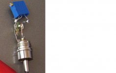
can you open it , and take few pics of output stage ?
Tea-Bag said:
That was interesting. 1K sine wave used.
830 ohms measured off of pot enabled RCA once removed from CDP.
So it's a highish output....
Mike
can you open it , and take few pics of output stage ?
Re: 832 ......... highish
Sure can, I will remove output stage from rest of unit.
It's full of SMD stuff, so I can't figure it out.
Wont be soon. Snowing terribly here, like 3-4" an hour, my back is toast already from shoveling.
 🤐 Opening gear only aggrevates it.
Zen Mod said:
can you open it , and take few pics of output stage ?
Sure can, I will remove output stage from rest of unit.
It's full of SMD stuff, so I can't figure it out.
Wont be soon. Snowing terribly here, like 3-4" an hour, my back is toast already from shoveling.
🤐 Opening gear only aggrevates it.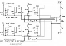
GuidoR said:Zen-modded version of B1, with j310.
Soon I'll post some pics of my version.
Thanks Choky😉
Sweet, No caps in signal path that I see.😀
Re: Re: Re: Re: Re: PSMLS dedicated buffer - schematic
Are the 4 buffers in the schematic for balanced inputs?
Zen Mod said:
schematic is in post 5 of this thread .........
or find final version attached .
JC = John Curl
EB = Erno Borbely
Are the 4 buffers in the schematic for balanced inputs?
Would the power supply in the PSMLS function well in Zen Mod's B1 ? Of course design would be modified to change +-12V to +-10V.
What sort of power supply did Zen Mod have in mind for B1? 🙂
I only ask because I need to build one for my B1 but if I build a PSMLS I won't need a B1 since PSMLS performs same function. 😕
😕
What sort of power supply did Zen Mod have in mind for B1? 🙂
I only ask because I need to build one for my B1 but if I build a PSMLS I won't need a B1 since PSMLS performs same function.
😕Zen Mod said:
pot - as a one whole , always have input and output impedance , pretty variable - depending in which position pot exactly is .....
Pumpie is made with 10Ks in input legs ; that's pretty same as input impedance of 10K or 20 K for unbalanced/balanced ;
in case that you want to use 50K pot - my advice will be to increase both input and feedback resistors - in same amount (with decreasing feedback cap )
B1 - Jfet stage itself is with mountain high input impedance ..... so just any pot is good enough , looking from Jfet side ...... but not for cable/capacity situation .
10 K ...... we can say that's ballpark
if you are using just LS ( without buffers) say that 68K-75K of power amp input impedance is lowest you can go .
in case that you are using LS with buffers - you can use as low as 600 ohms inputs 😉
btw - nothing can stop you to implement both outputs on your LS - buffered and non- buffered
I need to go reread this once my headache goes away.
I'm building a mauro myRef RevC and was going to pair it w/ a B1 to make an integrated amplifier. Now I'm thinking to use a PSMLS but I'm not sure how to verify the impedances of the PSMLS and myRef are complimentary. I'm going to use a Twisted Pear Darwin to switch my inputs. I wish I'd paid closer attention during my electrical engineering classes.

I did purchase an oscilloscope to help test my project -- so long as I don't blow it up. 🙄
Choky's design
Poor Italian Man artworked
TAKE CARE! THE PCB (COPPER SIDE) IS MIRRORED!
The size is the same and the PCBs can be staked with brass spacers (M3).
The shunts (positive and negative) are mounted in opposite.
(if U don't understand be patient - I'll post some pics).
Lego concept..😀
Poor Italian Man artworked
TAKE CARE! THE PCB (COPPER SIDE) IS MIRRORED!
The size is the same and the PCBs can be staked with brass spacers (M3).
The shunts (positive and negative) are mounted in opposite.
(if U don't understand be patient - I'll post some pics).
Lego concept..😀
Attachments
My pleasure!
An advice: wait for Choky's blessing...
I'm not responsible for the life of your J310s
An advice: wait for Choky's blessing...
I'm not responsible for the life of your J310s
GuidoR said:My pleasure!
An advice: wait for Choky's blessing...
I'm not responsible for the life of your J310s
who needs blessing from that pooftah Choky .......
anyway - you can implement 47nF ceramic cap from B to E of both Darlingtons ......
or even better - use exact schematic od shunt reg as in PSM LS buffer stage ( post #127 ) ;
I'll change few values , to accommodate it for J310 B1
depending of exact Ids of your J310 - source resistances are chosen for ~ 5mA through jfets
- Home
- Source & Line
- Analog Line Level
- Poor Serbian Man Optical Volume Control