The 2nd harmonic is the dominating distortion component. If overall THD is to be reduced, then 2nd harmonic must be reduced most.It will be a very bad thing to reduce only 2nd harmonic.
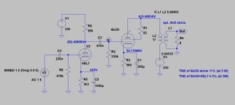
Attached is a quick simulation example I just made. THD of the triode connected GU50 alone is 11%. When combined with "badly" biased 6SL7 (which is now generating some 5% of 2nd harmonic distortion too), the overall THD of the whole amplifier is reduced to 5%. All the values are taken at 5 W.
And 2nd harmonic is still dominating component, some 15 dB above 3rd harmonic.
Attachments
artosalo,
You are someone who can run the 3 simulation tests that I proposed in my Post # 20.
Your circuit is perfect for the test, it is triode and triode wired output, and there is no negative feedback.
Instead of running it at 1 Watt, you might try it at 3 or 4 Watts.
Would you take the time and effort to do that, please?
Thanks!
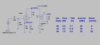
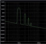
Triode wired GU50 SE (only) with constant input voltage (40 Vpeak) but with varying load resistance.
Attachments
Last edited:
Do you know that there are graphs exactly describing what you are trying to simulate in LTspice, I mean real world measurements?
Let me give you a challenge: simulate in LTspice my amp, and tell me parameters like bandwidth, output resistance, noise, distortion. I will measure also in real life, and will compare the measurements.
Let me give you a challenge: simulate in LTspice my amp, and tell me parameters like bandwidth, output resistance, noise, distortion. I will measure also in real life, and will compare the measurements.
Do you know that there are graphs exactly describing what you are trying to simulate in LTspice, I mean real world measurements?
Yes I know. In principle those are very similar to those which I just simulated. So what ?
Sorry. My ambition is not enough for that, but you can do that yourself if you see it necessary.Let me give you a challenge: .....
The only outcome that you will get is to see how far the used tube- and transformer models are from real component characteristics.
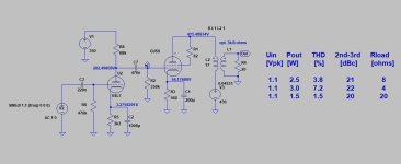
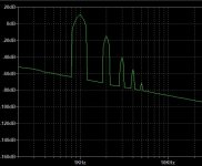
I am getting THD levels as yourTriode wired GU50 SE + 6SL7 biased for distortion cancelling:
I can be seen that distortion cancelling is effective at all (4, 8 and 20 ohms) load resistances.
Triode wired GU50 SE + 6SL7 biased for distortion cancelling without any modifications.LTspice is only for educational purpose when it comes to tubes.
Who said that I want lower distortion? I said that in triode mode the distortion is high!
Hello.
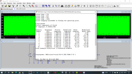
Here you have the simulation result in LTSpice and the measurement result of the same system, i.e. PSE_EL86 in a triode with an output power of 4.2W. I have a PSE_4P1L triode amplifier and the difference between simulation and measurement is 0.1%THD, i.e. for LTSpice simulation it is 0.4%THD and measurement is 0.3%THD with 4W output power.
Piotr
Attachments
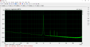
That does not mean anything, the program got it right for EL86.
With GU50 is different, the quality is excellent but the parameters vary widely, it is impossible for LTspice to get a sensible measurement.
With GU50 is different, the quality is excellent but the parameters vary widely, it is impossible for LTspice to get a sensible measurement.

Hello.
I don't want to prove anything to you, I've been designing amplifiers in LTSpice for a very long time and I've never been disappointed. To do an accurate simulation of your circuit you need to have the characteristics of your GU50 into a triode, just as you need the characteristics of the EC8010 you have. If you can, show the measurements of the amplifier.
Peter
Hello,
I do not know why some jump to make modifications, very strange.
Now I listen to unmodified amp, the exact schematic like in the first post.
The news are good, the sound mellowed from somewhat harsh and irritating, without loosing transparency. And these are only first 10hours, an amp stabilize after 200 hours+.
I do not like LTspice, I get all the info I need when I construct an amp the classic way, graphs and calculations. I think that is a matter of taste. We do not critic tastes, do we?
I will like to try some UL connection, to have a comparation with triode mode. Maybe I will post when I have all the data, we will see.
George
artosalo,
Thanks for doing that exercise!
1 stage:
For the output tube only, with constant level of 40V peak to g1:
The THD varied by 6.6% versus the load impedance.
The Delta of 2nd to 3rd varied 'widely': 9 dBc, versus the load impedance.
2 stages:
For the 6SL7 with 1.1V in, and the output tube at a constant level to g1:
The THD varied by 5.7% versus the load impedance.
The Delta of 2nd to 3rd varied by 'only' 2 dBc versus the load impedance.
So, for 1 stage the THD varied by 6.6% versus for 2 stages the THD varied by 5.7%.
Very little difference versus load impedance.
And, for 2 stages the Delta of 2nd to 3rd varied by 9 dBc, versus for 2 stages the Delta of 2nd and 3rd varied by only 2 dBc.
Lots of difference versus load impedance.
Of course, the 3rd harmonic was lower for the 1 stage, versus for the 2 stages.
Last edited:
I have done exactly that. Harmonic cancellation seem to have a narrow working window. For example, I tuned the first stage of a SE amp for minimum distortion at 10W, but then got worse figures at 8W. Also changing the load made a big impact.Now, take a challenge, and use that LT Spice program to do some real research about input stage 2nd H. distortion canceling with output stage 2nd H. distortion.
Triode Wire the output tube.
Remove any global negative feedback, local output tube cathode negative feedback, any Schade negative feedback, and any UL negative feedback.
That way, the real nature of the input stage and output stage 'cancellation' shows up.
Negative feedback can be applied later, after the study is done.
Set your amplifier software model for 1 Watt output, 8 Ohm secondary loaded with 8 Ohms.
Use an easy test frequency, 1 kHz.
Write down the input signal voltage that is necessary to get 1 Watt output 8 Ohm tap and 8 Ohm load.
Always apply that same input voltage, for tests 1, 2, and 3 below.
1. Load the amplifier output transformer 8 Ohm secondary with 4 Ohms. Check the 2nd H. distortion.
2. Load the amplifier output transformer 8 Ohm secondary with 8 Ohms. Check the 2nd H. distortion.
3. Load the amplifier output transformer 8 Ohm secondary with 20 Ohms. Check the 2nd H. distortion.
What did you just test? You simulated a real world loudspeaker.
You tested the input stage to output stage 2nd H. distortion cancellation.
But, the output stage 2nd H. distortion is not a constant when you change the load impedance (even though the signal to the output stage control grid is constant for all 3 tests above.
Have fun . . .
Prove me wrong.
Easy to do, since you do not even have to build anything, and you already have the software model for 8 Ohms on the 8 Ohm tap.
You only change one single parameter for the three runs of LT Spice: 4 Ohms, 8 Ohms, 20 Ohms.
Please report back your findings.
Thanks!
I'd say it does improve distortion, but it does not replace having two stages with good linearity.
PS I did that with a real circuit and also with Ltspice.
A generalization:
If you are trying to use the 2nd harmonic distortion reduction of a 2 stage single ended amplifier . . .
Getting it to work with a fixed 8 Ohm load on the 8 Ohm tap is one thing. It can be relatively easy and effective.
Then Getting the same amplifier, and the same 8 Ohm tap to drive a 4 Ohm resistor, or a 16 Ohm resistor, it is not as easy and effective in reducing the 2nd harmonic distortion.
But then comes the real challenge:
Driving a real world loudspeaker, with dominant impedances that are sometimes R, sometimes C, sometimes L, and sometimes a mix of RLC.
All but the Pure R, are elliptical loads. They are oval or circular load lines, not straight R load lines.
That can play tricks on an otherwise low distortion single ended amplifier.
It turns out that Push Pull amplifiers are better suited to drive elliptical loads; versus single ended amplifiers that are not as well suited.
But, admittedly, the single ended amplifier may sound better than the push pull amplifier, depending on all the particulars.
Of course, EC8010 and GU50 are different tubes, they distort differently.I have done exactly that. Harmonic cancellation seem to have a narrow working window. For example, I tuned the first stage of a SE amp for minimum distortion at 10W, but then got worse figures at 8W. Also changing the load made a big impact.
I'd say it does improve distortion, but it does not replace having two stages with good linearity.
PS I did that with a real circuit and also with Ltspice.
6A3sUMMER's point is more that the output valve sees a very very different actual load than the model assumes. Real loudspeakers aren't really even remotely a simple resistive load; they're motors, with big electromechanical dynamics, and with large parasitic reactances. Models are great, and all that, but you shouldn't actually believe 'em, unless you grew up with them, were mates in school, kept up, and then especially not.
All good fortune,
Chris
All good fortune,
Chris
An other generalization:
My opinion is that using a "reasonable" amount of GNFB is the best way to improve the performance of a tube amplifier.
Of course the basic design should be done as well as possible. GNFB is not a cure for bad design.
My opinion is that using a "reasonable" amount of GNFB is the best way to improve the performance of a tube amplifier.
Of course the basic design should be done as well as possible. GNFB is not a cure for bad design.
Actually they distort similarly (if GU50 is triode connected). For both 2nd harmonic is the dominating distortion component.EC8010 and GU50 are different tubes, they distort differently.
Attachments
- Home
- Amplifiers
- Tubes / Valves
- Poor man's 300B amplifier