The main idea of this article is that noise reduction as a goal is not alfa and the omega of power supply design. In the context of a Single Ended amplifier.) I'm not sure I 100% agree with the reduction to a single filter stage. This decreases the slope of noise reduction to 6db/octave, whereas 3 or 3 stages would have a noise reduction of 12db and 18db, respectively.
Could be if that is your thing. Rob's aim is to produce a good sounding amplifier.but we are trying to achieve DC
He is not using a 6x5. But something close to a 6X5. In any case remember transistors have ratings, tubes have guidelines. (He only uses the 6X5 for the sim)Isn't the 47uF capacitor he arrives at for the first cap too large for a 6x5?
Depending on what you've done with your psu, nothing different happens after x amount of seconds. The interesting thing is how the psu handles transients I think. (Although in a SE Class A amplifier the current draw is the same?)Most of his analysis centers around the first 10sec after turn-on. Shouldn't we be more concerned with the steady-state (ie...POST 10sec)?
And what I look for is a lack of ringing when there is a sudden change in current. Such as in my Ladyday psu.
Attachments
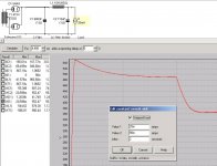
And here an "unstable" supply do demonstrate ringing when current demand is changing.
What is interesting is that after 10 seconds..this "unstable" supply will have LESS ripple. But does it sound better? Than one with slightly more ripple but one that is rock solid? I don't know. But the point is there is much more to a power supply than creating DC...IMO
What is interesting is that after 10 seconds..this "unstable" supply will have LESS ripple. But does it sound better? Than one with slightly more ripple but one that is rock solid? I don't know. But the point is there is much more to a power supply than creating DC...IMO
Attachments

Ok. I was wondering how to model current demand changes downstream and reflect that back to the model....you're suggestion to use the stepped current sink shows me how I can attempt that...
Ugh....this is frustrating.
I think I actually need to find a good spice package to model the PSU in conjunction with the actual Aikido circuit, so I can see how signal (in theory, anyways) and the 6SN7s affect the draw on the PSU.
Side question: why did you choose the 6x5 for your PSU board? Any particular reason? Does it have an advantage over a 5AR4 in this application.
By the way. Something that I only thought of after I saw John Broskie's boards.
If you have a common psu for both channels you could
 Compromised URL removed by Moderation
If you have dual mono psu's it's ofcourse best to give each board it's own psu noise divider. But for the frugals out there.
If you have a common psu for both channels you could
Compromised URL removed by ModerationIf you have dual mono psu's it's ofcourse best to give each board it's own psu noise divider. But for the frugals out there.
Last edited by a moderator:
No not really. The 6x5 is just a typical rectifier tube for a preamplifier.Side question: why did you choose the 6x5 for your PSU board? Any particular reason? Does it have an advantage over a 5AR4 in this application.
Got my boards today! Thank you!
I am quite impressed...they are very thick and sturdy boards. Well worth the money.
I am quite impressed...they are very thick and sturdy boards. Well worth the money.
Looks like they can take up 18 gage or so. I use 22, a little easier to work with.
Hay Bas, Got my boards. Thank you once again…John
Hay Bas, Got my boards. Thank you once again…John
I don't know...🙂 I don't even know what it is in metric measurements. I use cat5 cable.What "gauge" are the holes in the PCB?
I'm sorry Joe. I ran out of octal boards. The new batch of octals were shipped to me yesterday.Maybe mine will come soon.
If you have not received an email that they have been shipped. They have not been shipped.
Regards and apologies,
Bas
If I want to build out with all 6SN7s...
J1 - solder a straight wire across
RV2 - solder straight wires across all three (connect each side hole to the top hole)
For the rest of the resistors, use 2W for the large blocks and 1/2 Watt for the small blocks.
Is this correct?
BTW: why "RV2"? where is RV1?
J1 - solder a straight wire across
RV2 - solder straight wires across all three (connect each side hole to the top hole)
For the rest of the resistors, use 2W for the large blocks and 1/2 Watt for the small blocks.
Is this correct?
BTW: why "RV2"? where is RV1?
Talking about power supplies a while back I have astrange problem that does not make much sense.Thereis a bit of low level ps oscillation around 1 or 2 hz and in the mv range that also goes thru to the Aikido output.
My ps is diode bridge-10uf-1k-330uf-(300ohm-22uf)x2.It simulates well without problems.On the scope however the dc level has low ripple but seems to be wavering up and down around 100mv every once or twice a second irregularly.
The first question is- is this normal for a ps because of mains AC variations or is it motorboating?
Secondly why is this coming out of the output of the Aikido?My theory is that since the output is biased at half the ps voltage then with a high enough cap (I am using 1.8uf) this very low AC variation will also be reflected at the output even though the aikido is supposed to be ps immune.
I tried a capacitance multiplier which brought the variation to about 10-20mv on the output but it is still there.
I got curious and just put the scope to my power supply to see if could see the same thing.
First off my temp (how long has it been now?) junk box power supply looks just awful. I have some major ringing, yet the Aikido sounds good I was not able to see any slow shift
I would think that very small changes of the AC voltages would look like that. Do you have some other power supply you could measure?
The reason you can see it at the output is although the Aikido has good PSRR, it is not immune. What you have is closer to changes in DC level then ripple. Maybe a HUGE C-1 would stop it, but I doubt that is a good idea.
I will measure my other power supplies with the scope to see if this phenomenon exists .
However instinctively without calculating I think this should not happen to a Ps and much less to the output of a preamp.
Of course the mains AC voltage variation should slightly affect the dc level at the ps output but it should be much slower than 1or 2hz up and down all the time.I think it should normally drift a little of course but very slowly.It should not be visible on a scope set at AC.
Secondly the output of the pre should never have such an amount of oscillation for obvious reasons.Perhaps the aikido is particularly sensitive to this type of problem with its novel ps coupling technique.This oscillation is not something you can hear but inthe worst case I can see the woofer cones slowly move in and out.
Otherwise the ps ripple and general noise are almost unmeasureable at least on my scope.
I built a VTV linestage a few months ago - my first real DIY project-and hooked up a scope to see how stable the output was. I saw a voltage drift up and down every half second to second of 10 - 100mv. Thought it was motorboating or something. Hooked it up one evening and watched the scope for over an hour and couldn't figure out why the output seemed to drift a bit randomly. Then the fridge tuned on and I got a spike. Ah-ha. It looked like fluctuations in the AC supply. Hooked up a DVM to measure house voltage and saw it wantered. (Note - my DVM is slow so you see changes every second or two). That's what mine was - house voltage wanders. Even when nothing is cycling in the house, it drifts a bit. Could be what you are seeing.
- Home
- Amplifiers
- Tubes / Valves
- Poll..anyone interested in an Aikido linestage PCB group buy?