I was wondering if there was such a thing as colored pens for white sheathed hook-up wire, so that multiple combinations of stripes could be created to emulate that style of striped wiring above.
Et voilà: https://www.amazon.ca/Sanford-Marke...2&sr=1-1-12d4272d-8adb-4121-8624-135149aa9081

-Never use solder wire only as a glue. .... Solder is only to fix the joint, which has been made by twisting a wire around a terminal. Thats the way to do it right.
Who ever said that clearly never envisioned surface mount components. 😀 Now in everything you buy, the solder IS the conductive "glue" that holds it all together.
True in SMD and even in the ordinary PCB based gear. The problem with the electronics build using those production methods arises when circuits became more complex due to cheaper and smaller components like the transistor.
When looking at a relative simple schemo of a Revox G36 and its twelve active tubes, its much less complex designed than its successor, the famous A77 (transistor) tape machine.
With a tube amp, its relative easy to build with very few parts, because its ancient technology that still can sound superior. But when it comes to more complex gear, I think it makes sense to use PCB's.
Today, we see even tube amps, build inside the same way as every digital gear is being build. Some using SMD technology.
What I was interested in was to optimize for a special tone and that could be done more easily with gear that doesn't employ hundreds of parts.
I made comparisons about the sound of amps when soldered in a very time consuming and laborious way vs. quick and dirty methods. The wrap before solder method sounded much better. But it took its toll, a slow and time consuming method. And it needs experience. The more experience, the better the results will show a clean and nice looking internal construction. I'm not the master on that subject, but I enjoy some individual, handmade pieces of tube gear.
Attachments
Last edited:
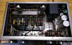
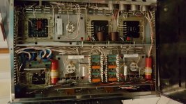
This could make for a great Xmas quiz: name the amp from the chassis view, and for a bonus point, which component is missing?
I don't get the idea why people build this style tube amps. Those, with added SMD computer PCB, could be bought in a trillion different versions on the asian marketplaces. They all look the same inside. PCB based tube amps with computer technology inside. Very cheap and readymade. No hassle with DIY necessary.They also produced progressively more complex designs... My last build also looked nice before I finished it. 😀
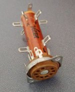
I use those IC caps... Did you recap or did Fisher also use them?
I bought this amp like this, cap already replace by the owner.
I did a full restauration using a restauration kit from a guy named "Metalbone" . (No affiliation with the guy)
This is what you get:
1. Bias Power Supply (bridge, electrolytic and film capacitors and resistor)
2. Power/Power Supply (current limiter, film capacitors [can caps not included] and diodes)
3. Amplifier Section (electrolytic and film capacitors and resistors. The full kit includes Sonicap Generaltion II coupling capacitors)
4. FM Signal Path (electrolytic and film capacitors)
5. Multiplex Section (electrolytic and film capacitors)
6. Heat shrink tubing
7. 1 full copy of the service manual (including schematic)
8. A 14-16-page detailed description (with photos) of how this kit was installed on another Fisher Receiver.
9. A reverse tube layout diagram for easy chassis to schematic reference
10. 1 additional copy of schematic for marking up (multiple pages)
So I ended up replacing those yellow cap anyway. Good kit. I also replace the Volume pot which is the ON/OFF switch at the same time.
One wonders what kind of failure rates they were seeing on those mass-produced point-to-point wired consoles and amps. At least I find it hard to believe that all units produced worked straight off the assembly line.
Tom
I had the same thought. And since sometimes bad solder joints don't act up for awhile what was the short term failure rate.
I would love to have seen the assembly line in process in action. And what was the employee turnover rate?
I don't get the idea why people build this style tube amps. Those, with added SMD computer PCB, could be bought in a trillion different versions on the asian marketplaces. They all look the same inside. PCB based tube amps with computer technology inside. Very cheap and readymade. No hassle with DIY necessary.
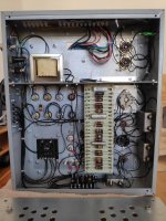
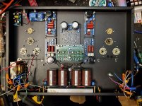
I built this as a test of the boards. I designed the VA/PI, preamp (actively loaded triodes) and driver boards... No computers though. This is an all analog design, even the AB-Q module which I didn't design. It's from Pavel at Audioamp.eu I will offer these boards for sale soon.
This is effectively the same amp (with added RIAA and 6E2 meters) but without the circuit boards... Just look at the left and right sides.
Attachments
Last edited:

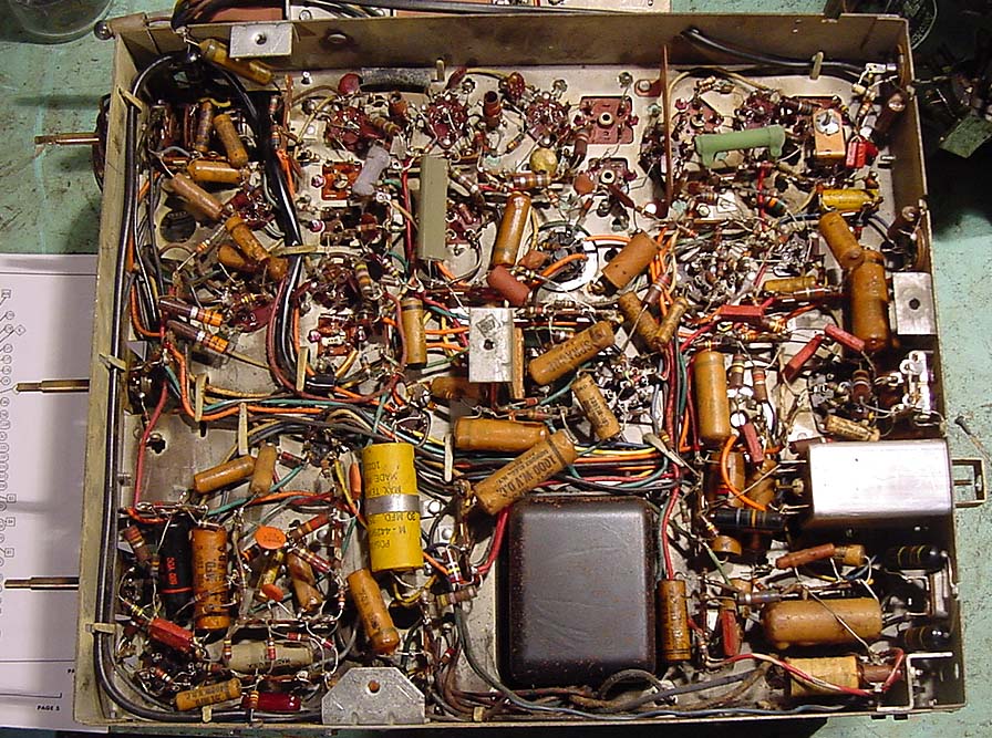
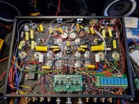
Very clean, but somehow I still prefer this 🙂
I refuse to take your comment as a seriously one (despite your attached "smiley") when I am looking at this picture.
It is: CHAOS for me........
is not "point to point" but "spaghetti" wiring.
Last edited:
I used to hand wire Allied / Knight kits, and Heath kits. I often had at least 3 wires in one eyelet hole on multi eyelet tie strips. I always wrapped the wires securely before soldering.
Back then, there were no Rhos material restrictions, so things soldered nice with 63/37.
Sorry to say, the kids of today can not find and build a Knight kit or Heath kit.
Most kits of today do not even begin to measure up to the old standards,
including the instruction manuals:
Cut a 2 inch black wire and strip 1/4 inch insulation from each end . . .
Connect one end of the wire to pin 1 of . . .
Use a # 6-32 1/4 inch screw and nut to mount the . . .
Look at the very well drawn schematic on page 49 . . .
And even with PCBs, install a 100 Ohm 1/2 Watt resistor into holes # 7 and # 8 . . .
Kit building is not what it used to be.
Can any of you remember what it was like back then?
And the kits were kept in their original state, no later modifications.
Wrapped wires that are around a post, or even worse wrapped after insertion into an eyelet hole are very hard to get out nicely in order to do repairs, or modifications.
If you worried about lots of wires going everywhere, and just a few colors of insulation,
then consider the following . . .
A complex piece of communication gear that used very small diameter wires that had all white insulation, with extremely small black numbers written on them, but they were all very tightly wrapped into a wiring harness.
. . . Better get out the schematic, you will never be able to trace the wires visually.
I can remember repairing old style circuit boards, without having a solder sucker, and no solder wick either, to safely get the part out, without destroying the PCB pad the part was soldered too.
I also remember SMT, and a prototype assembler that tried to save labor and process, gluing the SMT parts down, and then putting the board across a solder wave machine that had a wave larger than a surf in Hawaii during a storm.
18 SMT ICs with bad soldering . . . solder missing, solder bridges, etc. I needed an Eye Loop to repair those boards.
Each wiring technique has its tradeoffs.
I have known products of each technique that worked and/or sounded very good.
Most of all that is both an art and a science.
Last edited:
I refuse to take your comment as a seriously one (despite your attached "smiley") when I am looking at this picture.
It is: CHAOS for me........
is not "point to point" but "spaghetti" wiring.
Completely serious actually. At least if I was the one that wired it 🙂
"Sorry to say, the kids of today can not find and build a Knight kit or Heath kit.
Most kits of today do not even begin to measure up to the old standards,
including the instruction manuals"
But that particular picture is, in my humble opinion, not
"old standard". And, believe me or not, I am "old school" as
those kids are used to label us seniors.,
Most kits of today do not even begin to measure up to the old standards,
including the instruction manuals"
But that particular picture is, in my humble opinion, not
"old standard". And, believe me or not, I am "old school" as
those kids are used to label us seniors.,
- Home
- Amplifiers
- Tubes / Valves
- Point to point wiring