Regarding the H-K chassis in the first post, it's not that complicated if you don't let it be overwhelming. Circuit by circuit, it's straightforward. The original mfr cannot spend the time and expense on aesthetics that no one will see.
How do you eat an elephant?
How do you eat an elephant?
"Regarding the H-K chassis in the first post, it's not that complicated if you don't let it be overwhelming. Circuit by circuit, it's straightforward. The original mfr cannot spend the time and expense on aesthetics that no one will see."
Except for the repair engineer ..😱
But you are right I think. The average consumer would never take a look inside the chassis.
Except for the repair engineer ..😱
But you are right I think. The average consumer would never take a look inside the chassis.
There are many reasons for the pro's companies of those tube stone ages to establish a more structured, more repair friendly style. Time is money for the pro's. Best is to have gear or cards that are easily changeable in case of an emergency. Amps in magazines for example.
Attachments
There are many reasons for the pro's companies of those tube stone ages to establish a more structured, more repair friendly style. Time is money for the pro's. Best is to have gear or cards that are easily changeable in case of an emergency. Amps in magazines for example.
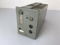
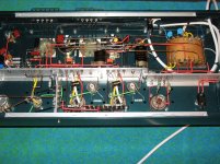
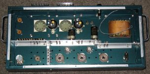
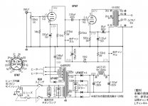
This picture is interesting. What is this for amplifier(?) ?
And ... "those tube stone ages" ? Absolutely not ! Alive and kicking!!
Last edited:
One wonders what kind of failure rates they were seeing on those mass-produced point-to-point wired consoles and amps. At least I find it hard to believe that all units produced worked straight off the assembly line.
Tom
Tom
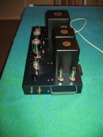
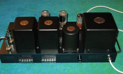
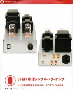
Point to point I made over 10 years ago. 6L6GC SE, tube rectifier, OA2 voltage regulation, ECC81 driver.
Attachments

AmadeusMozart,
Great layout, great planning, and lovely wiring!
What were the output tube types?
I hope you are still using that as one of your most listened to amplifiers.
I only put 1 handle on my amplifiers; your 2 handles are more symmetrical.
Great layout, great planning, and lovely wiring!
What were the output tube types?
I hope you are still using that as one of your most listened to amplifiers.
I only put 1 handle on my amplifiers; your 2 handles are more symmetrical.
One wonders what kind of failure rates they were seeing on those mass-produced point-to-point wired consoles and amps. At least I find it hard to believe that all units produced worked straight off the assembly line.
Tom
Very low failure rate - on average I managed less than 3 cosmetic faults on 19K solder points while working for Philips putting telephone exchanges together.
Components were tested before use.
And that's why we build our own!The average consumer would never take a look inside the chassis.
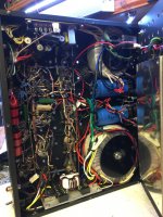
Absolutely not. There were two major faults been done:AmadeusMozart,
Great layout, great planning, and lovely wiring!
-never bend a wire rectangular and never use solid conductors for internal wiring.
Because it damages the structure of the wire and it reduces the diameter, too. You put the cable under stress by bending and stretching.
-Never use solder wire only as a glue. This has been done here all the time.
Because solder is a very bad conductor and with all those bad soldering joints, the result will be a poor performance compared to a better soldered unit.
Solder is only to fix the joint, which has been made by twisting a wire around a terminal. Thats the way to do it right.
One can see, not many have good knowledge and experience in building gear, even when it looks at a first glance to be made with a good practise.
In fact its not, its a good example of how it shouldn't been done.
But if you don't want to go for perfection, nevermind the bollocks. Looks pretty good in fact.
Last edited:
This picture is interesting. What is this for amplifier(?) ?
And ... "those tube stone ages" ? Absolutely not ! Alive and kicking!!
Its TAB V76M.Mess- und Anpassungsverstarker, Ampl/Mixer Tonographie
Last edited:
Semi Rigid coax Does have a minimum turning radius; but that is to keep the impedance a constant 50 Ohms all along the coax.
Waveguide also has a minimum turning radius, for the same reason (many waveguides are 200 Ohms, even though there is no center conductor).
Waveguide is the transition between coax and Free Space (Free Space is 377 Ohms if I remember correctly).
Of course, when I measured 500GHz on the world class spectrum analyzer we had, we did not have access to anything but straight waveguide.
And the harmonic of the almost 18GHz local oscillator was either the 28th or 29th harmonic to mix with the 500GHz to bring it down to the 3.5GHz or 10 GHz IF.
I doubt that the additional inductance by a sharp right angle on his wires will affect the response at audio frequencies.
And unless you have a conservatively large wire size, there will not be too much additional resistance due to the right angle. Perhaps a small wire that is running a few amps of filament current might be a problem.
On the other hand, if you bend a wire multiple times, or if you twist a wire multiple times, it may become work hardened.
And that IS a problem.
The most perfect square wave response I have ever seen from a tube amplifier was a co-worker's beautifully built push pull amp, and it had lots of wires with right angle turns, for both signal and power.
I think we are still at the outer layers of the onion.
With my 75 year old eyes, and my computer monitor, I was not able to see the solder job, and unwrapped wires that was only 'glue like'.
Sorry.
Last edited:
One wonders what kind of failure rates they were seeing on those mass-produced point-to-point wired consoles and amps. At least I find it hard to believe that all units produced worked straight off the assembly line.
Tom
I read at least for one manufacturer that the layout had to be electrically and mechanically secure before soldering, and was actually tested before being ‘fixed’ in solder. So I suppose the extra diligence gives greater reliability and accuracy. The throughput is going to be the main issue.

That one above shows how multi-colored wiring really helps. I have an old but fairly simple PSU, but all the wiring is in a threaded harness, and is all one color, so it is very difficult to trace it visually.
I was wondering if there was such a thing as colored pens for white sheathed hook-up wire, so that multiple combinations of stripes could be created to emulate that style of striped wiring above.
The shortest length of single core 0,36mm2 I could buy was 100m, so a couple of lifetimes at current progress.
Last edited:
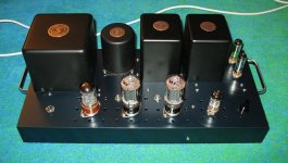
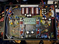
Agreed. Here is a hybrid point to point and circuit board amp I just built using colour coded wiring. The yellow caps demonstrate my laziness - they are 0.33u in series with the 1u on the circuit board. It was easier to tack them on than to take out the boards and replace the caps on them.
Attachments
That one above shows how multi-colored wiring really helps. I have an old but fairly simple PSU, but all the wiring is in a threaded harness, and is all one color, so it is very difficult to trace it visually.
I was wondering if there was such a thing as colored pens for white sheathed hook-up wire, so that multiple combinations of stripes could be created to emulate that style of striped wiring above.
The shortest length of single core 0,36mm2 I could buy was 100m, so a couple of lifetimes at current progress.
Hi There,
what about coloured heat shrink tubing? That will do
Greetings Ulf
- Home
- Amplifiers
- Tubes / Valves
- Point to point wiring