I don't want to double post, but I feel I need to express in this section again my BIG THANKS to Mark.
Mark has given us a little jewel with this astonishing filter. I found again another great application for my needs, with IMHO outstanding results. If interested you can read it in the VFET builder's thread:
https://www.diyaudio.com/forums/pass-labs/370689-diy-sony-vfet-builders-thread-207.html#post6829888
All credits to Mark: I end up yet again with some permanent parts of his inside my audio unit.
Enjoy music
Claude
Thanks for your kind words ,Mark!
It took finaly 2 of them to enhence the VFET - but I had 'in case of' everything ready to chain up to 6 of them 🙂
Enjoy your day very much and thanks again for this "wide purpose" little jem
Claude
It took finaly 2 of them to enhence the VFET - but I had 'in case of' everything ready to chain up to 6 of them 🙂
Enjoy your day very much and thanks again for this "wide purpose" little jem
Claude
I'm very interested in ClaudeG's experiment / findings, and also the possibility to replicate his solution on my v1 ACA.
Are there any concerns with the 3A max rating and the VFET? Will it cope well with the full requirements of the AMP?
Thanks for any insight!
Rafa.
Are there any concerns with the 3A max rating and the VFET? Will it cope well with the full requirements of the AMP?
Thanks for any insight!
Rafa.
Rafa, you may want to read again what I did.
The VFET draws permanently circa 3,4A. I don't doubt that Mark has dialed a safety margin with the board, plus I used 6A coils, so I "could" possibly use one filter for the entire unit... but 1) I hate to perform outside the specs on units I didn't design myself and 2) I had plans to split channels anyway.
Nevertheless, I personnaly wouldn't really use this filter over 3A, be it first and most because Mark didn't recommend it, and also because I feel once you get to the boundary of the specs another design might be better / more suitable rather than compromising too much with something that is trying to perform out of spec. As an example, one year ago I built another filter for Gilles, to cope with 5A loads...
In short, to comply with the above, each filter in my VFET "sees" roughly 1,7A at 36V, so works well within Mark's specs. The filters are in my case NEVER exposed to 3A, in fact 1.7A pass permanently through them... OK, perhaps a tad more at a very quick start up phase due to the additional caps I added... marginal here.
Another point...As noted elsewhere, some seemed keen on paralleling filters to increase the ampere capacity, but I wouldn't do that for balancing reasons, or at least have a close look at the various circuits - Me, not sure I have the right knowledge today, so I would rather avoid doing it. In the VFET, I am NOT paralleling filters as the input is indeed the same and splitted, but the outputs of the filters "never join again" and hence go different routes... each filter feeds only and strictly one channel (OS + FE).
Long story short: I never used these filters with more than 3A and wouldn't recommend doing it. That will stand unless the maker of the filter, and that is Mark only, tells us otherwise... or mods his filters / proposes another filter accordingly.
I hope this helps you Rafa, sorry if I am a pain with my long posts, I don't want to discourage, just to dissipate any potential confusion... I may have created 🙂
Claude
Last edited:
Thanks! Yes, I would never use it for more that 3A, as you: I trust Mark! I was really questioning if, inside the VFET, they are actually seeing more than 3A. If you know they are only seeing 1.7A, that's great, thanks.
Yes, that's it Rafa, and I just replied to your other (related) questions in the other thread.
I hope all is clear now, if not... just shout 😉
I hope all is clear now, if not... just shout 😉
An electricity usage monitor like one of (these on Amazon International) will tell you how many watts your VFET's Meanwell SMPS is drawing from the AC mains. It's a piece of test equipment that Demian Martin strongly recommended, in his 2021 Burning Amp presentation. Check out the video, it's extremely good.
The engineering datasheet for the MeanWell SMPS is attached below. It says the SMPS "efficiency" (= powerout / powerin) is 92% for the 36 volt model. So now you can calculate the output current of your Meanwell SMPS in your VFET amplifier:
SMPS_current_out = [ (Watts drawn from Mains) * 0.920 ] / 36 volts
Half of that flows in the Left channel circuitry, and half flows in the Right channel circuitry.
Since the Meanwell's MAXIMUM output current is 4.44 amperes (datasheet page 2), you know in advance that the calculation above will give a resulting SMPS_current_out which is some number less than 4.44 . The VFET amp was designed by Nelson Pass, and his design certainly does NOT attempt to operate the Meanwell SMPS beyond its datasheet limits (!)
Since SMPS_current_out < 4.44 amps, Left_channel_current < 2.22 amps and also Right_channel_current < 2.22 amps. Comfortably below 3 amperes in Claude's arrangement with separate filter PCBs for left and right.
_
Attachments
That is great to know! I guess that with the ACA with a 5A PSU (mine is 19V) it will be a similar maximum per-channel below the 3A, so that is great news. Thanks! One more thing from Mark to live inside our beloved pieces of equipment! 🙂
Thanks,
Rafa.
Thanks,
Rafa.
For folks who are waiting for low ESR capacitors to become available again, I see that Digi-key has a quantity of 470uF 35V ESR 26mOhm Kemets newly available. Everything else is sitting at zero in-stock.
Dimensions are .197, .394, .827 -- perfect for the PO89ZB when it's used at lower voltages in preamps, etc.
Digikey 399-6128-ND, Kemet ESY477M035AH4AA
Dimensions are .197, .394, .827 -- perfect for the PO89ZB when it's used at lower voltages in preamps, etc.
Digikey 399-6128-ND, Kemet ESY477M035AH4AA
Quite a few recent line-level projects here on diyAudio are using Switch Mode Power Supply ("SMPS") wall warts to convert mains AC into the DC needed by audio circuitry. To name a few recent examples, the Starving Student II headphone amp, the First Watt H2 effects box, the B1 Korg NuTube preamp, and the Amp Camp Preamp+ (with headphone amp) are all powered by external SMPS warts. It's definitely a trend.
PARTS LIST
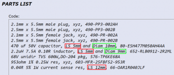
Code:2.1mm x 5.5mm male plug, xyz, 490-PP3-002AH 2.5mm x 5.5mm male plug, xyz, 490-PP3-002B 2.1mm x 5.5mm female jack, xyz, 490-PR-002A 2.5mm x 5.5mm female jack, xyz, 490-PR-002B 470 uF 50V capacitor, LS 5mm and Diam 10mm, 80-ESH477M050AH4AA 2.2uH 7.5A 0.10R inductor, LS 5mm and Diam 9mm, 652-RLB0912-2R2ML 68V unidir TVS 600W,DO-204 pkg, 576-TP6KE68A 953ohm 1% 0.25W res, xyz, 603-MFR-25FBF52-953R 0.04R 5% 1W current sense res, LS 12mm, 66-OAR1R040JLF
Great design, Mark - thanks! 🙂
It seems everyone is out of the last item - for quite a few months. 🙁
However, searching RS Components for "current sense resistors", I can find the following which are in stock:
1: Arcol Ohmite 50mΩ Fixed Resistor 2W ±1%
Arcol Ohmite 50mΩ Fixed Resistor 2W +-1% 12FR050E | RS Components
2. Arcol Ohmite 20mΩ Fixed Resistor 3W ±1%
Arcol Ohmite 20mΩ Fixed Resistor 3W +-1% 13FR020E | RS Components
3. Arcol Ohmite 20mΩ Fixed Resistor 2W ±1%
Arcol Ohmite 20mΩ Fixed Resistor 2W +-1% 12FR020E | RS Components
4. Arcol Ohmite 25mΩ Fixed Resistor 2W ±1%
Arcol Ohmite 25mΩ Fixed Resistor 2W +-1% 12FR025E | RS Components
5. Arcol Ohmite 30mΩ Fixed Resistor 5W ±1%
Arcol Ohmite 30mΩ Fixed Resistor 5W +-1% 15FR030E | RS Components
6. Arcol Ohmite 25mΩ Fixed Resistor 3W ±1%
https://au.rs-online.com/web/p/through-hole-fixed-resistors/1249286
Can I use any of the above for R1/R3?
Thanks,
Andy
Another one!
Another filter is working. It went together quickly and sounds good. I'd have a hard time describing it's effect on the ACP+ but in general it's clearer sounding with the filter. More better. The ACP is already a nice sounding piece and the power filter is only $10 ... it's an absolute no brainer.
Thanks to Mark for coming up with such a cool little circuit (and sharing it with all of us) and Tom and Elena for shipping out a couple of missing parts.
Unrelated to how it sounds, there is a typo on the paper enclosed with the kit. The first line of the parts list for the 0.04r resistor lists them as R1 and R4. It wants to be R1 and R3. The schematic on the reverse side is correct as is the board.
It's the best $10 I've ever spent in audio.
 High praise indeed, thank you!
For a real eye opener, price out the complete bill of materials (temporarily assuming everything is in stock, even though that's not true today), for 100 PCBs plus 100 full sets of all parts. When you decide to do all of the organization and sorting and inventorying work yourself, at a labor rate of $0.00 per hour, and a storage cost of $0.00 per cubic foot per month, and when you eliminate the "final hop" in the shipping chain, these SMPS filters become even more amazingly low-priced. Don't get me wrong, $10 is a terrific price and a hellll of a deal -- and everybody should buy five of them from the store right now. But when you take out your sharp pencil and remove the intermediate labor plus extra shipment, the raw materials cost is shockingly tiny.
It seems everyone is out of the last item - for quite a few months. 🙁
Digi-key has them, only difference is 1% vs 5%. 1,048 in stock
Digikey part# 696-1634-ND Mfr part# MSR1-0R04F1
RES 0.04 OHM 1% 1W RADIAL
$0.93000
0.449" L x 0.067" W (11.40mm x 1.70mm)
I recommend you exert yourself in sweaty labor, to discover the significance of the information in red boxes and green boxes
Thank you, Mark - I see it's the distance between the leads which is important.
According to the attached dwg, as the part is being used solely as a low-value resistor (there are no leads going off to a "current sense amplifier"), any low-value res should be usable.
So perhaps I can re-phrase my question:
* is the value of 40 milliohms critical ... or will 25 milliohms work just as well?
Thank you for finding them at DigiKey, @wapo54001 ... but I'm hoping Mark will confirm one of the resistors I found at RS Components is suitable, as it will be expensive (due to overseas shipping charges) if I have to place an order on Digikey just for the 66-OAR1R040JLFs.
Andy
Attachments
The kit is available at the diyAudio store. If you have a supply problem I can pass on a original PCB and all the components loose for free as I have one left over. The 470uF caps are Panasonic ECA1VHG471 but everything else as per the parts list.
The kit is available at the diyAudio store. If you have a supply problem I can pass on a original PCB and all the components loose for free as I have one left over. The 470uF caps are Panasonic ECA1VHG471 but everything else as per the parts list.
Thanks very much for your very kind offer, mate - but I need to build 6 of them, for the Meanwells which power my active rig:
* 3x Topping E30s (5v supply)
* nanoDIGI (12v supply)
* A2D converter on my phono stage (12v supply), and
* 4-way digital source selector (12v supply).
So I will be building them from scratch - no PCBs but a sheet of 3mm teflon to hold all the components ... and ptp wiring on the underside. (The teflon doesn't melt at solder temperatures. 🙂 )
And if I notice an improvement in SQ ... I'll build a 7th - for my 'Number9' TT motor controller (48v supply). 🙂
Andy
Interesting - entering the cct into LTspice and playing with the values of R1/R3, I got the following results (for a 50kHz signal):
• 50mohm = 100mohm total resistance 36dB down
• 40mohm = 80mohm total resistance 32dB down
• 30mohm = 50mohm total resistance 28dB down
• 25mohm = 40mohm total resistance 25dB down.
So I decided to order 50mohm resistors, for that extra bit of attenuation.
Andy
• 50mohm = 100mohm total resistance 36dB down
• 40mohm = 80mohm total resistance 32dB down
• 30mohm = 50mohm total resistance 28dB down
• 25mohm = 40mohm total resistance 25dB down.
So I decided to order 50mohm resistors, for that extra bit of attenuation.
Andy
This is addressed in paragraphs 3 & 4 of post #1 in the thread. Don't forget to add the DC series resistance of the two inductors and the resistance of the interconnect wires.
- Home
- Source & Line
- Analog Line Level
- PO89ZB, an inline DC filter for SMPS wall warts. Preamps, HPA, Korg NuTube, etc