But maybe I would not use Thorsten's circuit either... 😉
This is really proving to be the source of the headache. I really like the idea of using EL84s for the driver since I've used a lot of them in Matchless and Badcat clones in the past (albeit as output tubes not drivers). With the headache it's causing I may just switch to a simple 6SN7 design. Any particular reason you don't like Thorsten's circuit?
My end goal is to simply put 420V B+ on the EL84 input before the 12K plate resistor, with a little higher B+ on the 300B plate since Thorsten lists 420 entering AND exiting the OPT, which can't be right.
Add serial resistance makes it even slower responding.
Slower responding to what? I thought this was a class A amp

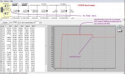
Here are some quick PSU II examples.
I basically re-created your supply as planned. Added a 100k shunt since you will want to do that in any case. You don't want those caps left holding a charge after you turn it off.
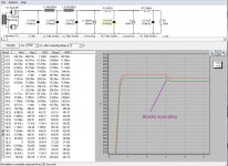
Then I created what a simple choke input supply might look like. Yes, the B+ is far lower, but then you need a different mains transformer. The sound will be MUCH better.
I basically re-created your supply as planned. Added a 100k shunt since you will want to do that in any case. You don't want those caps left holding a charge after you turn it off.
Then I created what a simple choke input supply might look like. Yes, the B+ is far lower, but then you need a different mains transformer. The sound will be MUCH better.
Attachments
Last edited:
Slower responding to what? I thought this was a class A amp
Just try it in PSU. Add serial resistance and see how it slows down the recovery time. Low DCR is something that you want to have.
It won't make a difference on a pre-amp that uses CCS or a well implemented shunt. But on an end stage, if your PSU is not low DCR you will definitely hear it. Especially for single ended class A.
Last edited:
You are simulating a load change and it's response time which is somethin his class A amp won't have under normal operating conditions.
A class AB push pull amp is another story.
A class AB push pull amp is another story.
You are simulating a load change and it's response time which is somethin his class A amp won't have under normal operating conditions.
A class AB push pull amp is another story.
Transients can cause funny things to happen in single ended amplifiers. And there is a reason we use tubes/valves - they can respond exceptionally faithfully to those transients.
Don't trust my word though. Trust George (Tube Lab) and others. Read what he writes on this page:
http://tubelab.com/articles/circuits/power-drive/
I think he has a nice way of summing it up.
Seriously. been there, done that. choke input will be about 1'000x better than cap input.
Last edited:
I just simulated a choke input supply using Hammond 282X and get a B+ of about 412V. However I still don't like the current draw... I still see peak currents over 300mA at the rectifier. Of course with your posted cap input supply, the peak currents are much higher than even that (over 750mA). What is the Transformer rating again?
Also, Your 300b's will need a separate, individual filament supplies. I suggest having a look at Pete Millet's or Rod Coleman's boards for this and being done with it.
Of course you're welcome to try AC filaments if you don't mind the hum.
Also, Your 300b's will need a separate, individual filament supplies. I suggest having a look at Pete Millet's or Rod Coleman's boards for this and being done with it.
Of course you're welcome to try AC filaments if you don't mind the hum.
Ok, so I did a nice example of choke input for you to see why it is desirable.
Please not "sand is better" comments from the sand PSU gurus who also lurk in these waters... 😉
oops I was wrong. Its much worse than what I wrote in these screenshots. 200ms settle time for the cap input supply is more like it. That will not sound good...
Even the choke input supply is 50ms, which I still don't like. I would suggest 20ms or lower is nice to aim for here.
Ian
This is really proving to be the source of the headache. I really like the idea of using EL84s for the driver since I've used a lot of them in Matchless and Badcat clones in the past (albeit as output tubes not drivers). With the headache it's causing I may just switch to a simple 6SN7 design. Any particular reason you don't like Thorsten's circuit?
My end goal is to simply put 420V B+ on the EL84 input before the 12K plate resistor, with a little higher B+ on the 300B plate since Thorsten lists 420 entering AND exiting the OPT, which can't be right.
Well.... el84 is one darn good pentode. if you really have a bunch of them then you can use it like Thorsten did. Don't let me dissuade you here. It will work. Lots of things don't work though - because driving the 300b grid is not trivial. You will introduce distortion with the pentode driver though. Maybe it will be ok for you.
For me personally, if I had to use pentode, then it would be triode strapped with a CCS or gyrator, using a mosfet follower to firmly drive the 300b grid with lots of swing and low distortion.
I would personally reconsider the regulated supply option.
If you can get your hands on some Tektronix iron, that'd be ideal for your application. and financially a rather attractive solution.
http://www.diyaudio.com/forums/tubes-valves/282274-tektronix-120-086-transformer.html
If you can get your hands on some Tektronix iron, that'd be ideal for your application. and financially a rather attractive solution.
http://www.diyaudio.com/forums/tubes-valves/282274-tektronix-120-086-transformer.html
In my 6HJ5 amp I have tried it all. I had a fully regulated "maida" regulator and I drove the 6HJ5 with a CCS loaded mosfet (Pete's A2 board). I tried high mu triodes and some pentodes before the mosfet for voltage gain. Lately I have gone full circle and ditched the regulated supply for a standard tube rectified CLCRC filter and I also ditched the power drive board and high mu front end for a 6N7 (both triodes in each envelope paralleled). I also got rid of the fixed bias for cathode bias. I don't know if it's the 6HJ5 but I like the lower voltage higher current setup I have now and a much simpler approach, it sounds lovely. I don't require much power for I am driving my Klipsch La Scala's with this amp. My point of the story is that at first I was hung up on making the amp technically perfect and at the end of the day I wanted to try a simpler approach because a lot of the amps I like are simple. I think it's important to have good quality decoupling caps, I parallel large motor run film caps with standard electrolytics. For some reason I didn't hear much of a difference between a regulated supply and non regulated supply and I just assumed it was because the DC current draw is relatively constant during operation.
Personally I think a choke loaded supply which does have better regulation is not warranted in these sort of designs. But maybe my hearing isn't up to par. We all are different so I am just sharing my experience. My advice would be to start simple and if you don't like the sound or just want to do tweaking then do the mods.
Personally I think a choke loaded supply which does have better regulation is not warranted in these sort of designs. But maybe my hearing isn't up to par. We all are different so I am just sharing my experience. My advice would be to start simple and if you don't like the sound or just want to do tweaking then do the mods.
My advice would be to start simple and if you don't like the sound or just want to do tweaking then do the mods.
I think the point is that there is no simple way to build a 300b.
Starting simple would make sense if the power supply cut the mustard. It doesn't. A quick simulation in PSU-II shows that the cap input supply as suggested for this circuit results in steady peaks over 700mA. The transformer is rated for 230mA.
The steady peak current draw for choke input supply would be significantly better at just under 300mA. But its still too high.
Ian
I would personally reconsider the regulated supply option.
If you can get your hands on some Tektronix iron, that'd be ideal for your application. and financially a rather attractive solution.
http://www.diyaudio.com/forums/tubes-valves/282274-tektronix-120-086-transformer.html
mr. sandman... build me an amp... build me an amp that is neutral like live music should be...
Don't make it blow-up or get hot like the sun... I wanna easy-peasey build that sounds really fun...
mr. sandman build me an amp.... 😀
It can be done and can sound great. I still prefer chokes though. 🙂
I think the point is that there is no simple way to build a 300b.
Starting simple would make sense if the power supply cut the mustard. It doesn't. A quick simulation in PSU-II shows that the cap input supply as suggested for this circuit results in steady peaks over 700mA. The transformer is rated for 230mA.
The steady peak current draw for choke input supply would be significantly better at just under 300mA. But its still too high.
Ian
http://www.hammondmfg.com/pdf/5c007.pdf
For full wave capacitor input load: I d.c. = 1.0 x SEC I a.c.
I see in post #23 that RMS current is: I(D1)rms = 259.78m
I agree it's on the high side but Hammonds are tough and I don't see him having a problem.
Here are some quick PSU II examples.
I basically re-created your supply as planned. Added a 100k shunt since you will want to do that in any case. You don't want those caps left holding a charge after you turn it off.
Then I created what a simple choke input supply might look like. Yes, the B+ is far lower, but then you need a different mains transformer. The sound will be MUCH better.
Your simulations don't take into account the output transformers though..
I asked about this on another forum, and I'm under the impression that the output stage plate current draw is not the same as B+ supply current.
Doesn't the stored flux of the output transformer core allow for high variation in plate voltage and current without affecting B+ output? And that, though this ultimately is supplied from the last LC pair in the filter, the input/output phasing relationships in the filter allow the transformer to supply current during conduction cycles while the filter dumps current as required.
now here is where the class A comes in to play. If the original post is correct, then it will constantly draw that current. You can't avoid that current draw in Class A.
Attachments

Last edited:
http://www.hammondmfg.com/pdf/5c007.pdf
For full wave capacitor input load: I d.c. = 1.0 x SEC I a.c.
I see in post #23 that RMS current is: I(D1)rms = 259.78m
I agree it's on the high side but Hammonds are tough and I don't see him having a problem.
I guess if you want to run the risk of your mains getting really hot and vibrating then go for it.
To avoid this, I over-spec my mains transformers. They only get a little bit warm to touch even after hours of use. Believe it or not, we get quite warm days in the summer and its nice to listen to music without contributing even more heat to the home environment.
I also use choke input because it helps keep my mains transformer cool. Think of it that way if you like. The choke can do a LOT of work if you let it. Or you can just use it as a filter...
Yes, I have had Hammond transformers. No, I don't agree that they are "tough". You tend to get what you pay for when you know what you're buying..
Last edited:
Doesn't the stored flux of the output transformer core allow for high variation in plate voltage and current without affecting B+ output?
Yes, one is the DC condition and the other is the AC signal condition.
I guess if you want to run the risk of your mains getting really hot and vibrating then go for it.
To avoid this, I over-spec my mains transformers. They only get a little bit warm to touch even after hours of use. Believe it or not, we get quite warm days in the summer and its nice to listen to music without contributing even more heat to the home environment.
I also use choke input because it helps keep my mains transformer cool. Think of it that way if you like. The choke can do a LOT of work if you let it. Or you can just use it as a filter...
Yes, I have had Hammond transformers. No, I don't agree that they are "tough". You tend to get what you pay for when you know what you're buying..
I run my tube amps all day long and the power transformers don't even come close to sweating, not even warm

After piles of reading I've taken Soulmerchant's advice for a choke input PSU. Have a look:

I've changed the PT to a Hammond 715 (1020VCT @ 300mA/450mA) for improved current handling. The input choke is a Hammond 193P (5H@500mA) and is overrated for the beating it's going to take. A 0.47uF cap was added to take a little load off of the input choke and adjust voltage. A Hammond 159T (2.5H@300mA) choke is there for additional filtering. R1 was changed to 235R since it will actually be two 470R resistors in parallel to feed both channels. With this setup I get 3mV ripple to the drivers and 25mV to the 300Bs.
Also, I went with 6AX4-GTB TV dampers in the rectifier for improved ruggedness.
Just for Soulmerchant here's the supply with a stepped load at 4 seconds.

Any thoughts?
I've changed the PT to a Hammond 715 (1020VCT @ 300mA/450mA) for improved current handling. The input choke is a Hammond 193P (5H@500mA) and is overrated for the beating it's going to take. A 0.47uF cap was added to take a little load off of the input choke and adjust voltage. A Hammond 159T (2.5H@300mA) choke is there for additional filtering. R1 was changed to 235R since it will actually be two 470R resistors in parallel to feed both channels. With this setup I get 3mV ripple to the drivers and 25mV to the 300Bs.
Also, I went with 6AX4-GTB TV dampers in the rectifier for improved ruggedness.
Just for Soulmerchant here's the supply with a stepped load at 4 seconds.
Any thoughts?
Last edited:
Choke or Capacitor Input?
"One puts up with these inconveniences when the amount of power to be supplied is so small that the extra cost of the components is not worth seriously bothering about, and especially when the load current is fairly constant, as it is for example when it consists of a Class A amplifier. The current peak can if necessary be kept within reasonable bounds by means of a resistor in series with the rectifier. And the system does have the advantage that the output voltage can be a fairly high percentage of the peak input voltage.
But for large power amplifiers, say 50 Watts or more, the extra cost of the rectifiers and transformer on account of the highly peaked current waveform is serious. What is perhaps more serious is that high-power amplifiers often work in Class B (or C), so the current drawn is liable to fluctuate between wide limits. The steep fall-off in output voltage when the current drawn increases, in short, the bad regulation is then a most undesirable feature of this capacitance-input power supply system."
- Status
- Not open for further replies.
- Home
- Amplifiers
- Tubes / Valves
- Please critique my PSU design