I guess that is what I saida chassis star would be the final destination for both the digital and analog 0V.
Looking further at TI SLEU037 doc(DEM-1794) you will notice that PCM1794 has pins 8,16,19,24,27 all tied together for agnd.I looked at the old BB PCM1794 evm already. The just ran everything on a common ground plane.
PCM1794A Vdd is derived from +5VA using a separate reg1117-3.3
CS8414 is all digital, they did not even filter the PLL supply.
They even say performance is degraded if you run the CS8414 from the +5VA supply, even using a separate reg, UP2,reg1117-3.3
This is why they put out these evm's to show us the way.
It also uses a lower performance DAC so you might not notice the performance impact on the grounding techniques. Having a solid ground plane also helps a lot too.Cirrus' Eval module is on one ground plane as well.
Last edited:
That makes sense. The extra wire length would help filter it as well.
Do you think this will be okay with remote regulation or should I wait for a shunt design to place near the devices?
An IC regulator (better than a 317) with possibly a touch of wenzel shunt after
it.
You would set 5.25V and 3.5V and shunt the excess voltage right at the
digital "customer" ( or real close). This is usually done with those precision
IC shunts , but they are relatively noisy as compared to the wenzel.
I wonder whether the TL431's 100+ nV noise would be real factor versus
the <20nV of the Wenzel ?
OS
Doubt it!! Even then, can you not filter the noise from the TL431 with LRC too.I wonder whether the TL431's 100+ nV noise would be real factor versus
the <20nV of the Wenzel ?
I read somewhere, someone said/measured that Onsemi tl431 are the lowest noise.
I'm not seeing much improvement with the Finesse regulator but I'm likely doing something wrong.
Yes , move the power source right to the wenzel shunt (bypass the 317).
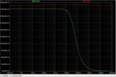
(below) notice the noise above 100K is reduced to a few nV , as compared
to the red plot (input).
It's the large semiconductor junction of the series pass device that's making
all the noise. All those recombining "holes".
The BCxxx shunts across it's R , with the noise signal applied though the cap.
The noise of the big semi is cancelled , and you have the shunt resistor
plus the BCxxx's noise remaining.
LF noise is taken care of by the 317 , it sucks above 50Khz.
Edit - combine the two (below2) , they work together to give @10nV noise/
PSRR still is at the sucky <80db 317 level ... but the noise is essentially gone.
(plots brought out to 10e7 / 100mhz).
OS
Attachments
Last edited:
Am I right in thinking voltage is going to move with load on the Wenzel shunt? I can see how the TL431 would remain stable but I don't see how the Wenzel would regulate it after the 15R resistor.
Am I right in thinking voltage is going to move with load on the Wenzel shunt? I can see how the TL431 would remain stable but I don't see how the Wenzel would regulate it after the 15R resistor.
I have all the tricks !
Take the 317's reference AFTER the wenzel (15R).
The 317's error correction sucks compared to the Jung.
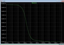
The circuit below kept 10nV noise and 5.1 - 5.17V output - no load - 250ma.
notice I played with the wenzel shunt I ( 10ma shunted).
The Jung will keep within pV output voltage hooked up in the same
manner.
OS
Attachments
That would pretty much require the LM317 needing to be close to the Finesse regulator. I was hoping to keep the LM317 or a low noise equivalent on the backplane and doing the fine filtering right at the DAC and WM8805. I may be able to put all this on board with smaller SMT LM317 devices though. I'm trying to keep this board under 100 x 100mm for the cheap production prices.I have all the tricks !
Take the 317's reference AFTER the wenzel (15R).
The 317's error correction sucks compared to the Jung.
The circuit below kept 10nV noise and 5.1 - 5.17V output - no load - 250ma.
notice I played with the wenzel shunt I ( 10ma shunted).
The Jung will keep within pV output voltage hooked up in the same
manner.
OS
That would pretty much require the LM317 needing to be close to the Finesse regulator. I was hoping to keep the LM317 or a low noise equivalent on the backplane and doing the fine filtering right at the DAC and WM8805. I may be able to put all this on board with smaller SMT LM317 devices though. I'm trying to keep this board under 100 x 100mm for the cheap production prices.
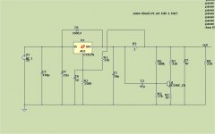
Well , the LP5907 is the equivalent of the wenzel circuit with it own
local error correction - good for <10nV noise @ 3.3V / 86db pssr.
And even a cheap .79c LP2951 kicks the 317's ar$e in psrr/noise/regulation.
(below) looks familiar . An slightly more crude Jung (on a chip).
Both are SMD and .79C , one as the pre-regulator for the other would
give 90% performance of a discrete Jung + wenzel
(@- 110db pssr and <20nV noise).
2$ digital bliss !!
OS
Attachments
Those look easy enough to work with. The LP2951s on the backplane and LP5907s right at the devices.Well , the LP5907 is the equivalent of the wenzel circuit with it own
local error correction - good for <10nV noise @ 3.3V / 86db pssr.
And even a cheap .79c LP2951 kicks the 317's ar$e in psrr/noise/regulation.
(below) looks familiar . An slightly more crude Jung (on a chip).
Both are SMD and .79C , one as the pre-regulator for the other would
give 90% performance of a discrete Jung + wenzel
(@- 110db pssr and <20nV noise).
2$ digital bliss !!
OS
Now the only thing left is the 5V analogue supply. Should we do another Jung or just shunt what we have?
OS and JW,
Should you change the title of the thread? I have been watching the two of you go back and forth and I'm seeing this as being more of a digital thread than as a pre-amp thread, am I missing something in what you two are creating?
Should you change the title of the thread? I have been watching the two of you go back and forth and I'm seeing this as being more of a digital thread than as a pre-amp thread, am I missing something in what you two are creating?
OS and JW,
Should you change the title of the thread? I have been watching the two of you go back and forth and I'm seeing this as being more of a digital thread than as a pre-amp thread, am I missing something in what you two are creating?
We're building a preamp/ input selector with an integrated DAC. Most of the preamp is analogue. OS has already got the analogue supply and linestages designed. I've built working prototypes. I'm just at the digital part of it right now. Next is the input/output selector and attenuation.
JW,
Do you have any idea at this point the cost for such a configuration? This sounds like it could work well in my self powered speaker where I was looking for a way to add a usb input section.
Do you have any idea at this point the cost for such a configuration? This sounds like it could work well in my self powered speaker where I was looking for a way to add a usb input section.
The DAC board will likely come in around $100. The linestage uses expensive op amps so it's around the same. It's hard to put an accurate cost on it. I buy all my parts in bulk whenever possible. Buying parts singly really changes the finished price.
Your speakers should likely have a specificly designed DAC/interface. I'm keeping this as adaptable as I can so it could be run from a rotary selector switch or an advanced control system or anything in between. I want to leave as many options as possible. This increases cost slightly, but increases size substantially. Once this is debugged it should be easy to design a miniature unit for your speaker by just cutting and pasting sections of this in Diptrace.
Thanks JW. I'll keep my eye on the goings on here even though I will admit this is way over my head and pay grade! I see some self powered speakers that are so cheap I just wonder how they do some of this for the price point. My speakers aren't intended to be a cheap set of speakers but I do have to watch the cost before they end up being in the audiophile price range, that would kill what I am trying to do. I'm already using a material for the enclosure that will cost more than most finished cheap plastic speaker systems by itself. but that is a compromise I am not willing to make, I know how much the enclosure will change the sound with cheap thin plastic.
Rsava would likely make your interface work great. I was chatting via email with LinuxWorks a few weekends ago. He's working on a cool sounding XBee interface that would work great with self powered speakers as another option. Possibly you could have good sounding and wireless speakers together in one package.
Now your talking wireless, oh my head! 😀
Believe me when I get this all together there will be those who will receive a nice package at their door one day with a set of these inside. I really appreciate all that I am learning and I still intend to reward those who have helped me finish this project. I could just build the speakers as just speakers and leave out the amp, and all the other things I think the current consumer market demands, some here would probably prefer I do just that and only build the speaker. But, I think that with the best electronics and putting the entire package together as a unit is the ultimate solution, no mixing and matching required. I still have to add an electronic xo and EQ to make all this work.
Believe me when I get this all together there will be those who will receive a nice package at their door one day with a set of these inside. I really appreciate all that I am learning and I still intend to reward those who have helped me finish this project. I could just build the speakers as just speakers and leave out the amp, and all the other things I think the current consumer market demands, some here would probably prefer I do just that and only build the speaker. But, I think that with the best electronics and putting the entire package together as a unit is the ultimate solution, no mixing and matching required. I still have to add an electronic xo and EQ to make all this work.
Do you have time to put together a 20,000 ft. block diagram of the overall direction and parts. What is the total price diy like for EVERTHING?😉We're building a preamp/ input selector with an integrated DAC. Most of the preamp is analogue. OS has already got the analogue supply and linestages designed. I've built working prototypes. I'm just at the digital part of it right now. Next is the input/output selector and attenuation.
- Home
- Source & Line
- Analog Line Level
- Pitchfork pre-amplifier