ready to put prts .. but running out of time ... may wait a few weeks ...
Have you made any more progress?
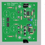
Here's a single sided layout of the Jung regulator alone for anyone who would like to use it for a preamp project. C13 and C14 are .1uf ceramic caps. They get soldered directly between pin 4 and pin 7 of the op amps under the board.
Attachments
They're looking tough to find. Tadya has some. BC560 BC560B Low Noise Transistor PNP
I would be surprised if those are the real deal.
I've gotten a lot of fake devices(both op-amps and transistors) from them.
I haven't bought a whole lot from them, but what I have has all been genuine parts. I prefer to buy from larger North American wholesalers though.
I am now ready to put parts but working on a budget and using some parts I have.
This is what I expect to use, of course LF356 & LM336 are more noisy but the most triky question is the value for R5 & R6 to get as much gain as possible without goin in oscillation..
This is what I expect to use, of course LF356 & LM336 are more noisy but the most triky question is the value for R5 & R6 to get as much gain as possible without goin in oscillation..
Attachments

R5 and R6 should likely still be 2R2. R7 and R10 are what adjust the output voltage. These should be pots. The inputs to the op amp are going to be operating 2V from their supply voltage with those reference diodes. Will the LF356 operate like that? LT1001 won't.
Lm 336 ara aviable at 2.5 volts but also at 5 volts and this is what I have but I will read more about LF356
5V will work fine. I thought they were 2V. Some op amps don't like to operate near their supply voltage, but 5V is far enough away.
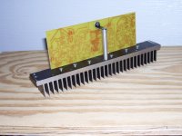
I now have the 2 regulators working using artwork on post 480 & schematic on post 487 .... next ... measuring noise & checking stability
Be careful if you use artwork from post 480 2 components are shown inverted ... a LED and a voltge reference.
Also there is one hole for a wire at -15 volt output that should be shifted about 0.3 '' otherwise the hole is under a capacitor.
Be careful if you use artwork from post 480 2 components are shown inverted ... a LED and a voltge reference.
Also there is one hole for a wire at -15 volt output that should be shifted about 0.3 '' otherwise the hole is under a capacitor.
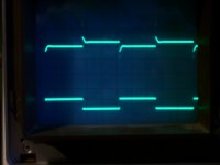
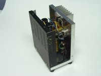
I did some test on the positive supply ..
I did use test load shown below gif attachement
On the scope had results shown in atttached JPG
Positive overshoot reach 0.13 volt.. negative overshoot 0.1 volt
Some part of these overshoot may be the effect of poor wiring around test jig
In steady state after overshoot I had around 15 mV of voltage variation
I did not test negative supply ..
I did test with the same load with a LM7915 used in my bench supply had less oveshoot but more noise that can be seen in the scope screen but impossible to show in photo .. visible as erratic spikes around traces ...
Attachments
OOOOOPS
I forgot to write
upper trace is power supply output 0.1 V/div
lower trace is transitor base signal 2V/div
I forgot to write
upper trace is power supply output 0.1 V/div
lower trace is transitor base signal 2V/div
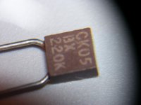
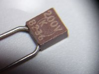
Mica or film are preferred over ceramic, but I'm not sure if you are going to hear a difference.
All ceramic caps are not created equal. Those particular CK05 types are not the best because then are probably not NPO(COG) grade materials, usually X7R. If they are like theseI have these ceramic capacitor and I expect to use them as feedback capacitor from output of opamp to inverting input .. is it a good choice or should I by mica capacitor ?
CK05 22 pF Multilayer Ceramic Capacitors MLCC - Leaded | Mouser
These are a better choices and alot cheaper than mica. You can always select RF grades if you want to pay more
22 pF C0G (NP0) Multilayer Ceramic Capacitors MLCC - Leaded | Mouser
Film in the feedback path is usually not used normally because of size.
Mica are at least 10x the price and usually not worth the extra $ unless you can prove to the bean counters otherwise 🙂
Last edited:
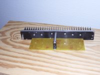
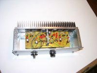
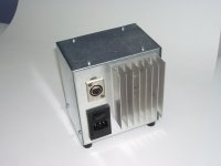
I did some more construction I did build the 2 diamondbuffer according to the attached JPG.
Both worked ar first time ... bias is around 110 mA and had below 50 mV of offset
Offset can be cured by adding an extra resistor in parallel with R1 or R2 ... so I did ... now offset is below 2 mV
Both worked ar first time ... bias is around 110 mA and had below 50 mV of offset
Offset can be cured by adding an extra resistor in parallel with R1 or R2 ... so I did ... now offset is below 2 mV
Attachments
- Home
- Source & Line
- Analog Line Level
- Pitchfork pre-amplifier