Selecting critical component ....
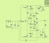
R9=1K & R8=4k7 set gain to 5.7 so 15dB and they are relativly low value to keep noise to a low value .. unfotunatly it does not match resistance on the other input of OP amp but I am afraid we must live with it.
R14= 100k & R11=1k & C2=33p set a low pass filter to 185kHz ( assuming pot to be set at 50% ) only to keep RF signal out.
C3 = 6.8uF & R10 = 68k bocck DC signal and make a high pass filter below 0.5 Hz
C1 = 180 p & R8 = 4k7 will limit high frequency response of the amplifier to 188kHz
As far as I understand all these values are suitable and should work ... if there is a mistake please tell me ..
Attachments
Audiofan,
Beautiful craftsmanship on your part. I am not an audiophile in the respect of so many individual enclosures but I appreciate the nice work you've done here.
Beautiful craftsmanship on your part. I am not an audiophile in the respect of so many individual enclosures but I appreciate the nice work you've done here.
Last edited:
I dont expect to drive headphone or other high current load ... so I did not include current limiting circuit .
Output bias is controled by T4 & T1 and is proportional to voltage drop across R3 & R4.
Output bias is controled by T4 & T1 and is proportional to voltage drop across R3 & R4.
probably know this but I'll say this for others that may contemplate following you,
the current limiting is a safety feature that adds protection against an o/p short or over load to ground, such as a shorted cable or comp down stream. these thing do happen in real life, regardless of the intended application, so that is why they are there. for the cost of the components certainly is a nice to have.
the current limiting is a safety feature that adds protection against an o/p short or over load to ground, such as a shorted cable or comp down stream. these thing do happen in real life, regardless of the intended application, so that is why they are there. for the cost of the components certainly is a nice to have.
If I have the circuit figured out correctly, with those parts missing the output transistors are going to burn up with posted values. Q11/12 (by my schematic) rob base current from Q9/10 to control class A current of the output devices. If it's not going to drive headphones, replace one of the three diodes with a 100R resistor and jumper another out to lower output bias (Ostripper's recommendation). If I recall correctly, three diodes would be 150mA, two diodes, 100mA, and one diode and a 100R resistor will be around 50mA through the output devices.
novel idea, sim the ckt like OS did, that will tell you what's up.
I did one better. I built it and got roughly the same results. I didn't try it without Q11 and Q12 in place though.
It is already buit and test ( tested only a few minutes without signal ) see post 489 & 499 it did work and bias was around 110 mA.
I dont see how this circuit can make a thermal runaway.
But I dont expect to have problem driving a power amp ... of course I may have forget something ...
With a short circuit at the output I think it will overheat and magic smoke could show up.
I dont see how this circuit can make a thermal runaway.
But I dont expect to have problem driving a power amp ... of course I may have forget something ...
With a short circuit at the output I think it will overheat and magic smoke could show up.
yep that is exactly how you want to too work 🙂With a short circuit at the output I think it will overheat and magic smoke could show up.
JW,
I started reading this thread when OStripper started it and it was just a concept. It seems somewhere along the way you took over the development of this project if I am correct. I know we all miss Pete and are wondering what is going on but in the meantime this seems to be your baby now. Could you summarize where you are now and what it is at this point you actually developed? That to me has gotten lost in the haze of development, what the final product has become.
Thanks,
Steven
OStripper was taking care of the analog design.I was trying to take care of the digital and mechanical side.
I've had test board successfully operating, but took a break to learn to write control software. The software is still a bit crude but operating.
I hope to come up with some final designs for the hardware soon. I don't like the big single board design I've got running right now and would like to go back to the earlier modular approach I started with.
Having built the preamp part to use it as a line preamp only,i was wondering if i could lower quiscent current bias to something lower like 16-20ma by changing resistors R4,R1 to 47 ohm.With current values of 220 or 330 ohm for R4,R1,output quiscent current is about 80-100ma.
Attachments
Ostripper had recommended altering the output stage current by changing the voltage drop across D3 and D4. Try replacing one or both with a resistor and tune the current from there.
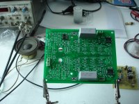
Construction is over ... first test ... bias & polarisation voltage
results ................
What's the IC you are using?
Is there a list of recommended chips beside the LT1028?
- Home
- Source & Line
- Analog Line Level
- Pitchfork pre-amplifier