I would have thought they would be NOS tbh (new old stock) but couldn't say for sure. It just wouldn't pay to have a semiconductor manufacturer produce these for the handful they would sell.
Are these diodes in thermal contact with the output stage ? As in touching the heatsink etc.
Are these diodes in thermal contact with the output stage ? As in touching the heatsink etc.
I found out about -g in another thread discussing options and someone replied pioneer selling them again.
As for diodes, yes they are on the heat sink. See image I posted in thread #32. The ones with white insulating wires at top of image.
As for diodes, yes they are on the heat sink. See image I posted in thread #32. The ones with white insulating wires at top of image.
Hi Tom,
Use the newer amplifier. You should probably change the speaker relay or risk degraded sound quality due to burned contacts.
These amplifiers do have speaker protection built in as you discovered. They sense DC offset which is the main concern for your speakers. What you shouldn't use are fuses because they have variable resistance as the element heats (which is how they work, fuses are thermal devices) as the volume increases. Variable damping. Use the other amp in your bedroom or anywhere you spend time. That would be a work bench or small office (computer area).
If the bias diode goes, you will lose control over bias current and possibly blow a fuse, or the output transistors. While a short DC potential across your speakers is undesirable, they shouldn't be damaged as long as the DC Offset protection is working. It may also have a temperature cutout too.
I'd say enjoy your work and keep an ear out for hissing, clicks or AC hum. Those are your warning signs aside from the huge "thump - click" if the amp goes DC.
-Chris
As for diodes, yes they are on the heat sink. See image I posted in thread #32. The ones with white insulating wires at top of image.
I see...
That could make for interesting experimentation if you got interested in all this.
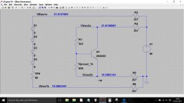
Modern amps use what is called a 'vbe multiplier' which is an NPN transistor (totally non critical) that would take the place of the diodes. The transistor has the bias preset (your VR4) wired to the base. This allows the bias to be set and also the temperature of the output stage is tracked and compensated for.
This shows the diode chain and the vbe multiplier for comparison. Ignore the resistors to the right, they are just to 'power' the two versions in the simulation.
Experiments and Relay
Mooly, I'm not sure I'm ready for that experiment 😱
Chris, argh...I was hoping one of you didn't suggest the relay was suspect and needed replacement. That sucker is sandwiched between two boards, both of which have a number of wire wrap connectors that would need removal (and accurate re-assembly). See first image. The relay is located about the middle of the board in the lower left (upper left actually, near the power caps, the way the image is getting rotated when you open it) of this image. I've also uploaded closeups of the replaced components on the Power Amplifier Assembly Board top and bottom. Bottom shows new shiny solder points compared to other original points.
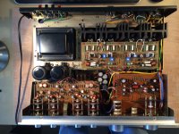
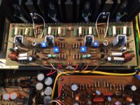
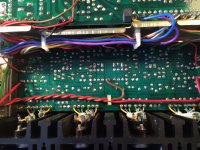


Well, funny thing. I just noticed a sticker on the back of this amp indicating repair work by a local company. That along with the shop's owner's name, Brett and the date 8-22-14 written on the chassis as you may see in the photos I just posted. I have contacted them to inquire what work they did. I'll let you know if/when I get a reply.
Hi Tom,
Good luck with that, seriously.
When an amplifier fails, the relay is instantly suspect. It makes no sense to repair an amp and live with poor connections to the speakers.
The top board will come out nicely if you remove the two diodes and rotate the PCB towards the front, screws removed of course!
-Chris
It would be interesting to know the amps history if the repair place is forthcoming with any info. I wouldn't perhaps hold out much hope though.
Unless you have wire wrapping tools you'll never be able to get as good a connection as the original joints unless you solder them. Solid core wire can fracture easily too, so if you do undo any, make sure you strip back to clean untwisted wire before resoldering.
Relays are funny things... one of the most common failure modes is simply the contacts oxidising and tarnishing partly because in normal use, the speaker current is so small. Typical symptoms are low and distorted sound that's worse at low volume. If you crank the volume up, the fault mysteriously disappears as the higher current punches through the oxide layer, only for the fault to return some time later.
Hi Mooly,
Yes, absolutely. Those relays can be cleaned if you know how. Either way, the relay has to come out.
-Chris
Yes, absolutely. Those relays can be cleaned if you know how. Either way, the relay has to come out.
-Chris
You were posting 😉 I was typing 🙂
I'd agree with your suggestion on replacing the relay on any amp that's seen any real DC 'fault action'. Breaking a few amps of fault current that's flowing in an inductive load is tough on any contacts.
I'd agree with your suggestion on replacing the relay on any amp that's seen any real DC 'fault action'. Breaking a few amps of fault current that's flowing in an inductive load is tough on any contacts.
Hi Mooly,
We've all been there, both posting while typing and having to replace a relay when it was the last thing in the world you want to do.
Tom, if you think your relay is hard to get to, I'd invite you to change relays in a Marantz 4400 quad channel unit. Just use patience and common sense and you will be fine.
-Chris
LOL, you guys are killing me. So I searched and found someone restoring an SX-1250 and this appears to be the same relay as my SA-8500. My service manual has it labeled as ASR-010-0
From the SX-1250 thread:
S1: ASR-010 MY4-02-DC24 relay: 653-MY2-02DC24
But if you check mouser.com for the first number (MY4-02-DC24), that is a 4PDT (4 Form C) Contact Form, where as the second number (653-MY2-02DC24) is a
DPDT (2 Form C) Contact Form. Not sure why he has it listed this way unless its a typo, as...
Looking at his before and after pix, it looks like both the original and replacement were MY4-04 (4pt), so that sounds like the same guy I want. But to be sure, I should pop the board and see the writing on the relay...
Haha Chris, I knew there was a reason I should steer clear of Marantz quad units (or any other quad unit for that matter)!!! I've decided in my vintage selection that I am going to focus on amps vs receivers, as there are fewer parts/boards on the inside to go bad and I just don't listen to the radio...ever. I play strictly vinyl and occasionally my iPod. Also, I have Sirius satellite radio on my TV/Surround Sound/DVD/CD driving a new pair of Wharfedale Diamond 10.4s. So I'm happy on that end.
Plus the cabinet I have won't accommodate most of the receiver beasts of the 70's...except the Marantz 22xx line...and I did have my eyes on a 2240 recently ;-)
Plus the cabinet I have won't accommodate most of the receiver beasts of the 70's...except the Marantz 22xx line...and I did have my eyes on a 2240 recently ;-)
You could always strip one of the old amps and put a nice 😱 chip amp in there 😉
I wouldn't like to say on the relays, not without being there, measuring the dimensions and checking the pin out form and so on. Coil voltage and coil resistance are the two other important factors.
I wouldn't like to say on the relays, not without being there, measuring the dimensions and checking the pin out form and so on. Coil voltage and coil resistance are the two other important factors.
Relay
Mooly, I would like a copy of these LTSpice files when I get around to installing the software. That's really cool stuff!!!
So, I had a look at the relay. And while it is in between two boards (tone board above and power/protection board below), I can access the relay contacts to de-solder/solder from the bottom, and have clearance to pop it out and reset a new one without pulling the top or bottom board. I was also able to move the tone board enough to get a look at the make/model number on the top of the relay and it is an Omron MY4-02 DC24, the same make and model as the one I found on mouser. It is a 4 point relay. The solder points on the relay look original, so I'm guessing the previous work on this unit did not include replacing the relay.
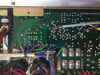
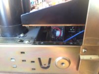
Here are some pix of the relay. The solder points are 14 point grouping near the blue and purple wire post connections.


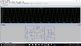
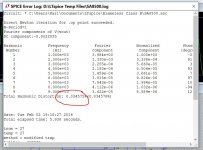
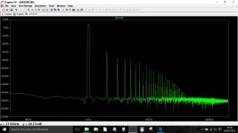
Here are the two LT files (the simplified front end and the full amp) and a text file which contains some of the transistor models used.
The simplified file will run straight off in LTspice. The other needs the text file for the models which simply means that you just keep them together in the same folder.
For example, just create a folder called say 'Pioneer SA8500' and place all three files in there. Clicking either of the .asc files will automatically open LT and load the file.
Attachments
I'd be very tempted just to clean the contacts on the relay tbh. The clear plastic top should just pop off. Get some clean paper (A4 stuff you would use in a printer) and cut a strip and bend it double, soak in alcohol and pull it gently through the contacts.
This shows me doing similar on a micro switch on a CD player.

This shows me doing similar on a micro switch on a CD player.

OK, I'll pull it this weekend and give it a look over/cleaning. If it looks suspect I'll order a new one.
- Status
- Not open for further replies.
- Home
- Amplifiers
- Solid State
- Pioneer SA-8500 Voltage/DC Offset Issue
