Hi everyone, thought I would check here for some thoughts before dropping my SA-8500 off at an electronics repair place in Baltimore. I picked this unit up last weekend for $20 due to pre-existing issues with the amp and protection relay kicking in after a few seconds of running. I measured the DC offset at the speakers and was seeing less than 10 mV on the left channel, but the right channel was up around 150 mV. Brought it home and followed service manual to measure and adjust internal voltage and idle current. I can get the left channel adjusted to 0 V. But the right channel is running at 40 Volts and adjusting VR2 has no effect. (I also found threads that discussed the service manual typos regarding VR1, VR2, VR3 and VR4).
Anyway, does anyone have advice on pinpointing where the issue likely is? Is this a cap issue or what? Thanks in advance.
Tom
Anyway, does anyone have advice on pinpointing where the issue likely is? Is this a cap issue or what? Thanks in advance.
Tom
does anyone have advice on pinpointing where the issue likely is? Is this a cap issue or what?
The power supply is shared, so that's ok. It's not likely a capacitor problem, maybe a blown output device, emitter resistor,
or solder joint. Measure the 0.5 Ohm resistors connected to each of the 4 output device emitters per channel.
Also check the 4.7 Ohm resistors on each base terminal. If you have a DVM with a diode function, check the BE and BC
junctions on each output device.
Last edited:
Hi rayma. All 4 0.5 Ohm resistors look good on each channel as do the 4 4.7 Ohm resistors on each channel. I've looked everything over and don't see any signs of overheating top to bottom, or any signs of swollen or leaking capacitiors. After looking things over, cleaning things up, dexoit on all pots and switches, Left channel appears spot on when I adjust VR1 to 0 volt and VR3 to 30 mV. But Right channel fluctuates constantly on ground and #16 anywhere from 0 V to -16 V. Adjusting V2 or V4 don't seem to have any effect.
Hi rayma. All 4 0.5 Ohm resistors look good on each channel as do the 4 4.7 Ohm resistors on each channel.
If you have continuity from the device emitter pin to the 0.5 resistor lead, that should be ok.
Have you replaced the 220uF 6V electrolytic capacitor in the feedback network to ground?
If not, use a same or larger value, non-polarized type, of as high a voltage as will fit the space.
Hi Tom,
Often, a resistor can burn open leaving only a small black spot on the body on the PCB side. The one and only way to check a resistor is to measure it. Often it must have at least on lead disconnected from the circuit to get an accurate reading. If you had an open emitter resistor, the voltage drop across it would make it appear to be good. There are times when you have to measure the component isolated from the circuit.
You have a voltage amplifier problem, not a current stage issue most likely. Excessive current would certainly point to an output stage problem. Look at the input pair and VAS (voltage amplification stage) for problems.
Pioneer did have an issue with open and shorted input capacitors. If they short, you can get a huge DC offset that cannot be adjusted. Disconnecting the input capacitor is the only way to test for that unless you simply replace them.
When measuring bias or other voltages in the output stage, use the speaker output source (between the two emitter resistors) as your meter reference (negative lead). Then your reading will be stable and be much more useful for voltage drop readings.
-Chris
Rayma, my proficiency with electronics is mediocre at best. While I play a software developer at work, my biggest accomplishment with vintage gear was recapping the crossovers on a pair of HPM-100's. So I'm not sure what the feedback network is, but I do see a pair of 220 uF 6.3V cap on the same board as the .5 and 4.7 ohm resistors. Are you suggesting that the fluctuating voltage is likely a capacitor issue? If so, I can give it a shot and order a couple of new ones?
Are you suggesting that the fluctuating voltage is likely a capacitor issue?
Possible, and I'd also go with Anatech's suggestion of the input caps, 0.47uF/25V.
He has direct experience with fixing these, and knows typical problems in them.
Again, use nonpolarized, with a voltage rating as high as will fit. Be careful soldering the pcb.
Last edited:
Can one of you point me in the right direction. I have the service manual and schematics, but I'm afraid I'm not that wise on the interpretation. Where do I locate the input caps you two are referring to?
Looks like you are getting some good advice but if you can post the circuit diagram then we stand a much better chance of giving more specific answers.
OK, looked over diagrams in the back of the Service Manual and it looks like the ones I need to look at/replace are C1/C2: Electrolytic 0.47 uF 25V and C9/C10: Electrolytic 220 uF 6V. I would have posted a photo of my board but looks like I can't do that directly here.
I've found the circuit, yes C1 and C2 are the input caps and these can be removed as a test. C9 and C10 must always be in place but can be substituted by anything from 47uf up to 1000uf as a test.
Not sure where you are up to on this but have you (with the power OFF confirmed that the 0.5 ohms are not open circuit ?
Also I see this amp uses the dreaded STV-4H 'series diode' device. You can actually short that out as a test and the amp will work OK but with a little increase in distortion.
The vital measurements to confirm.
1/ That the 0.5 ohms are intact and OK (resistance check with the power off)
2/ The voltage across the STV-4H must not be over around 2.3 to 2.4 volts. If its much over that then the device is faulty.
3/ For no good reason (other than its a typical type of failure mode) I would look carefully at Q5 and Q6...... but the clues will all be there in the voltage measurements you do.
Hi Mooly. So...
1. Yes, I checked all the 0.5 ohms and they all look good with power off.
2. Just checked the STV-4Hs and both are at 2.3 V with power on.
3. Don't think i have the skills to test transistors.
I don't have any spare caps around, so I am going to be making a parts list for a Parts Express order.
So far:
2 x 0.47 uF 25V Electrolytic
2 x 220 uF 6V Electrolytic
There are a couple of other pairs of Electrolytics on this board so I thought I might order them as well:
C3/C4: 33 uF 16V
C11/12: .47 uF 50V
Last edited:
You've checked the resistors by measurement ? not just visually. Very important. They would either be open circuit or OK.
Checking transistors in circuit isn't very conclusive unless they are short circuit but voltage checks show problems.
Without wanting to step on anyone's toes I wouldn't order any parts yet, at least not until you are reasonably sure of what has actually failed. If the 0.47uf was faulty then removing it would restore all the DC voltages to the correct value Proof it was faulty.
If you put your meter on DC volts and with the black lead firmly on the metal chassis, what is the DC voltage at the junction of all those 0.5 ohms ?
I checked ohms across resistors yesterday with power off and they all measured 0.5 ohms. I'm off to shovel some snow, so I will check the voltage a bit later today. Thanks again for your input Mooly!
I'll look at removing the right channel 0.47 uF as well later today as well.
I'll look at removing the right channel 0.47 uF as well later today as well.
That the resistors read OK is a good sign. The voltage should be near zero at the junction of them all.
Worth checking if its a mile out would be the DC voltage across the base and emitter of those two transistors I mentioned, Q5 and Q6 (depending which is the faulty channel of course). It should never be over around 0.6 to 0.7 volts. If it is then the device is faulty. Be very careful measuring voltage like this, one slip and it could all go pop.
Worth checking if its a mile out would be the DC voltage across the base and emitter of those two transistors I mentioned, Q5 and Q6 (depending which is the faulty channel of course). It should never be over around 0.6 to 0.7 volts. If it is then the device is faulty. Be very careful measuring voltage like this, one slip and it could all go pop.
Mooly, the left channel 0.5 ohm resistors are all at 0 V, but the right channel are all at 40 V. Not good, right?
As for Q5 (Right) and Q6 (Left), I followed the following article and measured them with my volt meters diode setting.
Meter Check of a Transistor (BJT) : Bipolar Junction Transistors - Electronics Textbook
Q6 (Left):
1+ and 2-: 720
1- and 2+: OL
1+ and 3-: 733
1- and 3+: OL
2+ and 3-: OL
2- and 3+: OL
Q5 (Right):
1+ and 2-: 740
1- and 2+: OL
1+ and 3-: 751
1- and 3+: OL
2+ and 3-: OL
2- and 3+: OL
I traced the electrical paths and numbered each lead the same with each transistor based on where it went. So according to the article, my #1 lead is the Base and my #3 on each is the Emitter (higher reading than the #2 lead).
Am I reading all of this right? From these transistor tests with power off, it would seem to me that both seem to be operating at a similar spec.
So, I'm assuming next test is to measure voltage between Base and Emitter with power on?
40v isn't good 😉
I'll mark the expected voltages on the diagram, and then if you compare against those then hopefully something might show up.
Yes, voltage across the B-E junction with it on... but be very careful.
I'll mark the expected voltages on the diagram, and then if you compare against those then hopefully something might show up.
Yes, voltage across the B-E junction with it on... but be very careful.
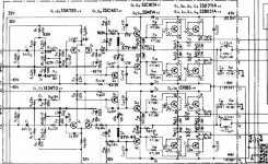
Thinking about it and this might be easier...
We know you have 40 volts on the speaker output marked with a red blob here. Lets work back from that knowing you have this incorrect 40 volts.
Points A through to F should also have 40 to 41 volts present. See if there is a sudden discrepancy with any of these showing a wildly different voltage.
If point A and B are at 40 volts or so then you need not check the other points at this stage.
- Status
- Not open for further replies.
- Home
- Amplifiers
- Solid State
- Pioneer SA-8500 Voltage/DC Offset Issue