Anand and Gyuri, many thanks, I'm really glad you like it 🙂 

Yes 🙂Wow! And just more while you're at it, a back panel view?

Yes, from Neutrik.What type of connectors did you use for the power supply to amp chassis? Speakon?
Yes I think so too! It’s just the „wrong hands“ I would be worried about. (Murphy is everywhere)
Sorry, of courseHopefully/most probly powercon (not speakon)?
 32A PowerCON:
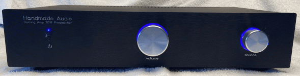
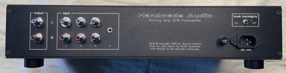
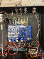
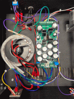
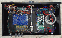
A friend recently asked me to build him a new preamplifier. He specified that it had to be simple and reliable. The result was a BA2018 powered by a VRDN.
Once again, I am grateful for the contributions to diyAudio by so many people, in this case most especially Wayne Colburn and Mark Johnson.
Regards.
Once again, I am grateful for the contributions to diyAudio by so many people, in this case most especially Wayne Colburn and Mark Johnson.
Regards.
Attachments

A knob-lights-switch! A mini-jack-input! A ... Penny&Giles?
that's really darn cool, like, woaah!
that's really darn cool, like, woaah!
Wow, that looks awesomeA friend recently asked me to build him a new preamplifier. He specified that it had to be simple and reliable. The result was a BA2018 powered by a VRDN.
Once again, I am grateful for the contributions to diyAudio by so many people, in this case most especially Wayne Colburn and Mark Johnson.
Regards.
Here are my Balanced F4 Monoblocks finally singing away!
My Yamaha RX-A6A has Balanced outs for the Front R&L.
Each of those are fed into a Schiit Valhalla 2 headphone amp on Hi Gain mode.
They feed the amplified Balanced into my F4s.
It took a bit of fidgeting to get it working correctly but they sound fantastic!


My Yamaha RX-A6A has Balanced outs for the Front R&L.
Each of those are fed into a Schiit Valhalla 2 headphone amp on Hi Gain mode.
They feed the amplified Balanced into my F4s.
It took a bit of fidgeting to get it working correctly but they sound fantastic!
Some goofy one off of eBay.Very nice job. What power supply board is that?
It uses common cathode dual diode to247 things.
BUT it uses them as a FWCT design.....
Totally threw me for a loop as I stared at it.
But it all came out +-24 on the other end.....
LOL
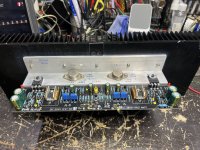
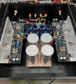
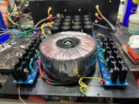
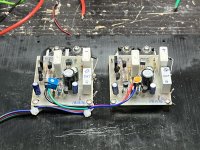
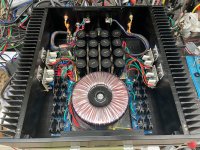
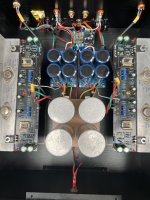
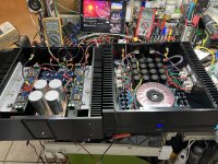
My DIY ONY VFET R0 build. Decided to use my power supply from my SissySIT amplifier. This was built in a two chassis configuration. Amplifier and power supply in separate enclosures. However there is an issue. SissySIT supply rail is 24 volts vs Sony VFET of 28V. After some thoughts I decided on a variable power supply up to 33V DC rail which could be reused as a common power supply.
This was accomplished with 28Vac 1KVA transformer with a variable series regulator. Regulated supply was frowned at for loosing dynamics. One reason could be due to small post regulation capacitance. This could be overcome with huge and equal pre an post regulation capacitance banks. Only disadvantage is double capacitance with added cost. As this is going to be used as a common (reusable) programmable power supply for all future power amplifiers then it is justifiable.
The Sony VFET amplifier uses DiyAudio store PCB. Building was straightforward with the very well laid out PCB. Following very carefully step by step using the excellent detailed testing notes made the adjustments very easy without any complications. DC and bias adjustments were completed smoothly. DC offset was minimal in the few millivolt range and bias was stable.
For the VFET, I used Sony K60/J18 combo.
Amplifier sounds fantastic.
Thanks to Mr Pass for designing and sharing this great amp.
Here are some photos:
Attachments
-
 DD1201E8-B5BF-4287-9E27-CE2D18398026.jpeg654.1 KB · Views: 423
 -
 3B50F6BB-6241-44BE-A5F6-DE14F39436C8.jpeg571.9 KB · Views: 407
 -
 A82C87CC-9C92-4888-89DC-2B2A23DA1FBB.jpeg565.4 KB · Views: 407
 -
 CDF5589D-5645-457C-B8E5-863AFAED04DF.jpeg546.2 KB · Views: 405
 -
 8F03DCA0-300F-4CBC-872C-6340C106D350.jpeg727.5 KB · Views: 408
 -
 782236CF-A69D-469A-8C03-4E098FC4E7CE.jpeg566.7 KB · Views: 397
 -
 4CB9F0E7-98E3-42D4-81CE-1292B49C8167.jpeg721.4 KB · Views: 415
@Plott if you don't mind me asking, who did you get to make the custom top plate for you? It's very cool, I wish I could find someone to do this out in Dubai... I know a shop in Budapest that probably could but I'm rarely in Europe these daysThat's a really cool build @tanwa !!! I like it very much
I would like to show my M2x in this "show-thread" too:
View attachment 1104899
View attachment 1104904
All the plates (top, rear, front) are made by Schaeffer AG in Germany https://www.schaeffer-ag.de/@Plott if you don't mind me asking, who did you get to make the custom top plate for you? It's very cool, I wish I could find someone to do this out in Dubai... I know a shop in Budapest that probably could but I'm rarely in Europe these days
You can download the designer software from the homepage in order to make your own designs; you can upload the finished designs directly from the software and a week or so later you have your plates.
The top plate is a two part thingie, the black plate is part of the Mini Dissipante chassis. I just wanted to pimp it 🙂
- Home
- Amplifiers
- Pass Labs
- Pictures of your diy Pass amplifier