
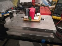
Vanilla B1 with smps filter. I may be making an integrated out of it with an ACA mini so no enclosure yet. Anyway, it's not sexy but it's working 🙂

No picture of the front with meters? 😎Build a Sony vfet amplifier with k60 / j18 without matching. Initially only with 2 pairs of k60 / J18. The sound is beautiful and a little hot. Then add another 2pairs of parallel k60/j18.
I see so many WHAMMY's where people struggle to install boutique OP-AMP because of the voltage rails' decoupling caps being too big.
The absolute maximum cap size for OP AMP decoupling that will ever be required is... 22uF in a combination with right-next-to-Vcc/Vee pins decoupling (underside), via the shortest possible path to ground, of around 0.1uF in SMD flavour (per each rail). This combination will also provide great current delivery speed to OP AMP, at all audio frequencies (and beyond). If 0.1 SMD sounds too fast and clinical, just use a 0.1uF MKP film cap from WIMA. This will sound fantastic, not to mention that a high speed OP-AMPS will be easier to use and implement 🙂 with no oscillation issues.
few screen captures....
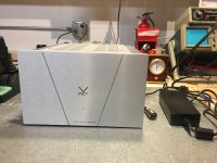
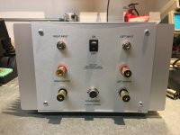
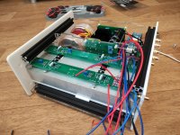
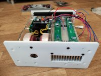
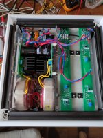
I finished my 2SK60 VFET part 3 amplifier today, it's been playing music for hours now. I have the Theseus PSFLT and Nimitz FE with Tucson daughter boards from my M2X build. I also have Austin, and Mountain View to try out later. Dead quiet and sounds awesome! Has to be the easiest amp to set bias!
No turn on or off thumps with Mark Johnson's designed PSFLT set to 5 seconds. The only changes I made were using Nichicon capacitors since the Panasonic caps were on back order. I did use mica and goop instead of the silicone pads provided in the OS kit and Nichicon LKG Type 3 (Super Through) output caps on the Nimitz FE (I had them in stock).
Many thanks to Jason, Mark Johnson and of course Nelson!
Attachments

Lovely build, congratulations @elwood625 !! I imagine some folks on the VFET threads might want to learn from your construction experience (and parts selection!), perhaps especially so with the DC input jack and the DPDT (!!) on off switch.
Here are pictures of my "ACA on steroids" which I started in 2015 and just recently finished (except for the power supply enclosure). It's a fan-cooled Amp Camp Amp using IRFP150Ns as the output devices and running on 26 volts. Connects to the PS with a 9-wire umbilical. Sounds great, but I still have to tweak the fan speed to take the heat. Pictures of the guts and additional details available at the build thread: https://www.diyaudio.com/community/threads/aca-concept-ii.283344/


Thank you Patrick. That spalted wood (not sure of the species) came from an old pallet; it was quite the lucky find. The rest of the pallet (not spalted) was used for a greenhouse bench. Not sure what I'm going to use for the PS enclosure... maybe some leftover flooring I have (engineered... alder, I think).
How did you do the logo in steel ?
Etched ?
Try Noctua Fans. Worth the money :
https://noctua.at/en/products/fan
Patrick
Etched ?
Try Noctua Fans. Worth the money :
https://noctua.at/en/products/fan
Patrick
Yes, etched. Quite simple, really. I built a little etching unit consisting of a transformer and a basic bridge rectifier + smoothing cap. Added a potentiometer to adjust the output voltage and a switch that bypasses the rectifier to output AC. You use it in DC mode to etch, and in AC mode to mark without etching. It delivers up to about 10 VDC or 12 VAC. The business end is a wood block with a piece of sheet copper glued to one side, with a tab to connect an alligator clip to. You can also just use a cotton swab. I just cover the copper plate with a piece of felt held in place with a rubber band, wet it with some lightly salted water, and etch away...
Very interesting! You are etching steel with salted water and galvanic? Great!Yes, etched. Quite simple, really. I built a little etching unit consisting of a transformer and a basic bridge rectifier + smoothing cap. Added a potentiometer to adjust the output voltage and a switch that bypasses the rectifier to output AC. You use it in DC mode to etch, and in AC mode to mark without etching. It delivers up to about 10 VDC or 12 VAC. The business end is a wood block with a piece of sheet copper glued to one side, with a tab to connect an alligator clip to. You can also just use a cotton swab. I just cover the copper plate with a piece of felt held in place with a rubber band, wet it with some lightly salted water, and etch away...
But how to transfer the image to the steel?
BTW, I also used the same rig to copper plate the logo, although I should have laid on a thicker layer of copper... it's pretty faint.
I used photosensitive PCB solder mask paint. I applied a layer of the paint to the steel, positioned a positive transparency of the logo, and exposed it to sunlight for a few minutes. Washed away the un-polymerized paint with the appropriate solvent (I forget which solvent), leaving metal exposed where the logo would be. The only problem with solder mask is that it's pretty tough when cured; impervious to any solvent that I could find. So I had to scrape it off using a razor blade. I'm sure there are other options out there that are easier to remove.
FW F5, common PS, active PWM cooling
Attachments
-
 IMG_20220628_120857.jpg573.1 KB · Views: 456
 -
 IMG_20220628_120857.jpg573.1 KB · Views: 435
 -
 IMG_20220628_134135.jpg611.7 KB · Views: 437
 -
 IMG_20220628_134750.jpg602 KB · Views: 439
 -
 IMG_20220628_134815.jpg440.7 KB · Views: 464
 -
 IMG_20220629_163557.jpg358.4 KB · Views: 458
 -
 IMG_20220629_163602.jpg495 KB · Views: 454
 -
 IMG_20220629_163615.jpg254.7 KB · Views: 439
 -
 IMG_20220701_143950.jpg253.3 KB · Views: 461
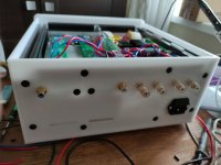
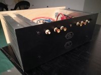
What's the enclosure made of? POM?FW F5, common PS, active PWM cooling
plexiglass with laser cuttingWhat's the enclosure made of? POM?
As you can see I did not make the PCB because I want to build amplifier DIY as much as possible. The feedback is omitted. Mosfets are IRFP044 and they have biased at 2A. The power supply is C-L-C (33000uF-1mH-33000uF).
Relay board on torroidal transformer (2x30V AC, 400VA) is driven by Sonoff (WiFi Wireless Smart Switch) reprogrammed for three functions - ON/OFF main switch, soft start for transformer and speaker ON/OFF switch.
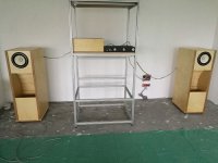
Finally, ZEN amp is meet his "older brother" Balance Zen Line Stage, and new speaker boxes with Fostex FE208E Sigma. Sound - beyond expectation. Hum is barely audible (speakers is 97dB), very detailed sound.
Relay board on torroidal transformer (2x30V AC, 400VA) is driven by Sonoff (WiFi Wireless Smart Switch) reprogrammed for three functions - ON/OFF main switch, soft start for transformer and speaker ON/OFF switch.
Finally, ZEN amp is meet his "older brother" Balance Zen Line Stage, and new speaker boxes with Fostex FE208E Sigma. Sound - beyond expectation. Hum is barely audible (speakers is 97dB), very detailed sound.
Attachments


- Home
- Amplifiers
- Pass Labs
- Pictures of your diy Pass amplifier